4.1.2.4 BLE Deep Sleep Advertising
Getting Started with Peripheral Building Blocks
Introduction
This document will help users to enable "Deep sleep" mode with BLE Advertisements on WBZ351 Curiosity board using MPLAB Code Configurator(MCC). In this basic application example the Deep Sleep advertisement interval will be set to 1000 millisecond. The advertisement interval will dictate the application Deep sleep time.
Users of this document can choose to just run the precompiled Application Example hex file on the WBZ351 Curiosity Board and experience the demo or can go through the steps involved in developing this Application from scratch.
These examples each build on top on one and other. We strongly recommend that you follow the examples in order, to learn the basics concepts before progressing to the more advanced topics.
Recommended Reads
Hardware Required
| Tool | Qty |
|---|---|
| WBZ351 Curiosity Board | 1 |
| Micro USB cable | 1 |
| Power Debugger/Multimeter | 1 |
SDK Setup
Software
Smartphone App
Microchip Bluetooth Data
Programming the precompiled hex file or Application Example
Programming the hex file using MPLABX IPE
Precompiled Hex file is located in "<Harmony Content Path>\wireless_apps_pic32cxbz2_wbz45\apps\ble\building_blocks\peripheral\deep_sleep_adv\hex" folder
Follow the steps mentioned here
Caution: Users should choose the correct Device and Tool information
Programming the Application using MPLABX IDE
Follow steps mentioned in of Running a Precompiled Example document
Open and program the Application Example "ble_deep_sleep_adv.x" located in "<Harmony Content Path>\wireless_apps_pic32cxbz2_wbz45\apps\ble\building_blocks\peripheral\deep_sleep_adv\firmware" using MPLABX IDE
<Harmony Content Path> how to find what is my Harmony Content Path
Demo Description
This Application Example enables users to enter Deep sleep mode while transmitting Connectable, Undirected BLE Advertisements. On power on reset application will enter "Deep Sleep Mode". When the USR-BTN 2(SW2) is pressed, the device on-board LED(green) starts blinking to denote start of advertisements. The device will enter into Deep sleep mode periodically based on the advertisement interval. The advertisement interval is set to 1000 milliseconds for this example. When device connects with the mobile App the onboard led start to glow solid, which indicates the connection established and the device will enter Standby Sleep Mode during Idle state.
Testing
Connect the WBZ351 Curiosity board to PC, program the precompiled hex file or application example as mentioned. Upon flashing, there will not be any indication on the board, since the device enters deep sleep mode. User can press the USR-BTN 2(SW2) available on the board to start Deep sleep Advertising. To connect to the WBZ351, User can open the Microchip Bluetoth Data App on Smartphone. Select the BLE Smart sub app to see the scan results. Device name "BLE_DSADV" will appear.

Current Consumption Measurement
Connect the Multimeter/Power Debugger to Power Measurement Header J6. Power on the Board. If using Power Debugger, users can use Data Visualizer to measure the current consumption.
Current measured in Deep sleep mode is around 1.9 uA.

Current measured in Deep sleep + Advertising mode is around 130 uA average.

Users of this Early adopter package should go through the known issues document and understand the limitations if any with the current low power mode implementation.
Developing the application from scratch
In this section we will see two possible ways to develop this application. In the first section user can make use of the import method available in the MPLABX Code Configurator. This is the easist and quick way to recreate the application with the help of import component configuration. In the second section, the user can experience the complete application development from the scratch using the MPLABX Code Configurator.Developing this Application using MPLAB Code Configurator Import method
This section explains the steps required by a user to develop this application example using MPLABx Code Configurator import method.
Tip: New users of MPLAB Code Configurator are recommended to go through the overview-
Create a new MCC Harmony Project -- Refer to the New MCC project Creation Topic.
-
Import component configuration --This step helps users setup the basic components and configuration required to develop this application. Users should follow the instructions mentioned here to import the component configuration.
Tip: Import and Export functionality of component configuration will help users to start from a known working setup of configuration
-
Accept Dependencies or satisfiers, select "Yes".
- Verify if the Project Graph
window has all the expected configuration.

Developing this Application from scratch using MPLAB Code Configurator
This section intented to showcase the complete application development from the scratch including the individual component and its dependency inclusion.
Tip New users of MPLAB Code Configurator are recommended to go through the overview-
Create a new MCC Harmony Project -- Refer to new MCC Project Creation
- In the previous step, the BLE
Stack component is included. Accept all the component auto-activation and
attachment auto-connect confirmation.

- Include the RCON Component from
the peripheral category.

-
Include the Transparent Service and Transparent Profile component located at :Harmony-> Wireless->Drivers->BLE
Establish the link between the Transparent Service and Profile

Click on the "Transparent Profile" component. In the configuration option, enable server role

-
Click on the BLE Stack component present in the project graph. A configuration option window will get open.
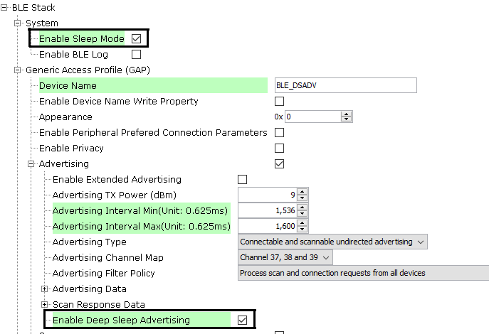
Enable the check box for "Enable Sleep Mode" option.
This action will trigger the auto inclusion of the RTC component . Accept the confirmation and auto-connect request.

-
Final Project graph with all the required component

Component configuration settings
- Select BLE_Stack
component in project graph.

Note: Advertising Interval Min can be modified to adjust Deep Sleep Advertising interval.
Tip: Advertisement payload can be configured by user here.
- Select clock configuration.
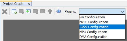
Configure RTC clock configuration.
 Note: Even after enabling and selecting the SOSC as backup source in the clock configuration. The LPCLK and RTC clock still show as 0Hz. This is a known issue which will be resolved in upcoming MCC release. For the time being, to fix this issue, a manual application code modification is necessary. The required change will be discussed in the next section.
 - Configure LED GPIO Configuration.

Note: The above GPIO configuration is used for indication of the device state in this example and is optional.
Tip: The configuration bits will be generated after user Generates code.
-
RTOS Configuration
Increase the Total heap size from the default value
Generate Code
Now all the required components has been added to the project and necessary configuration modification is made. The next step is to generate the application code.
To generate the project, follow the instruction on how to Generate Code
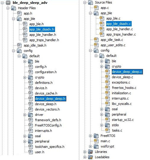
After generating the program source from MCC interface by clicking Generate Code, the BLE configuration can be found in the following project directories.
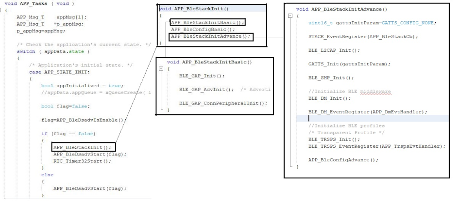
The OSAL, RF System, BLE System initialization routine executed during program initialization can be found in the project files. This initialization routine is automatically generated by the MCC.
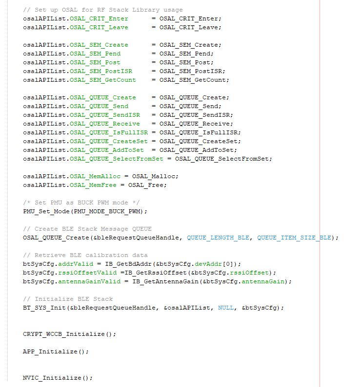
The BLE stack initialization routine excuted during Application Initialization can be found in project files. This intitialization routine is automatically generated by the MCC. This call initializes and configures the GAP, GATT, SMP, L2CAP and BLE middleware layers.
During system sleep, clock (system PLL) will be disabled and system tick will be turned off. FreeRTOS timer needs to be compensated for the time spent in sleep. RTC timer which works in the sleep mode is used to accomplish this. RTC timer will be initialized after BLE stack initialization.
| Source Files | Usage |
|---|---|
| app.c | Application State machine, includes calls for Initialization of all BLE stack (GAP,GATT, SMP, L2CAP) related component configurations |
| app_ble.c | Source Code for the BLE stack related component configurations, code related to function calls from app.c |
| app_ble_handler.c | All GAP, GATT, SMP and L2CAP Event handlers |
| app_ble_dsadv.c | Source Code for utilizing the deep sleep advertising functionality |
| device_deep_sleep.c | Source Code for deep Sleep and wake up related system configurations |
Tip: app.c is autogenerated and has a state machine based Application code sample, users can use this template to develop their application.
Header Files
ble_gap.h- This header file contains BLE GAP functions and is automatically included in the app.c file
Function Calls
MCC generates and adds the following code to initialize the BLE Stack GAP, GATT, L2CAP and SMP in APP_BleStackInit() and Deep Sleep Advertising Functionality in APP_BleDsadvStart(flag) functionAPP_BleStackInit() and APP_BleDsadvStart(flag) are the API's that will be called inside the Applications Initial State -- APP_STATE_INIT in app.c.
Manual Application code edit
This section talks about the mandatory code modifications that needs to be incorporated inorder to implement the deep sleep Advertising functionality.
Step 1: app_user_edits.c
- Some of the Harmony 3 generated files cannot be fully configured by the MPLABX
Code Configurator. This file contains the instructions for the user to modify
these files.
Follow the instruction mentioned on the app_user_edits.c file and after completing the required edits, comment out or remove the #error line
Step 2 - Initialization.c
- Comment the code inside
SYS_Initialize function
In the MCC Generated code, the CLK_Initialize and ROM functions are by default present inside SYS_Initialize function in Initialization.c file. The user needs to comment out the code referring to CLK_Initialize and ROM functions in SYS_Initialize function and should add under _on_reset() function in same initialization.c file.

- Code Inclusion inside _on_reset function
The previously commented code inside SYS_Initilaze function is included here

CLK_Initialize();
    typedef int (*FUNC_PCHE_SETUP)(uint32_t);
    ((FUNC_PCHE_SETUP)(*(uint32_t*)0xF2D0))((PCHE_REGS->PCHE_CHECON & (~(PCHE_CHECON_PFMWS_Msk | PCHE_CHECON_ADRWS_Msk | PCHE_CHECON_PREFEN_Msk)))
                                    | (PCHE_CHECON_PFMWS(2) | PCHE_CHECON_PREFEN(1)));
    //Set RF as idle mode
    RF_SetIdleMode();
- Code Inclusion inside SYS_Initialize function
-
DEVICE_DeepSleepWakeSrc_T wakeSrc; DEVICE_GetDeepSleepWakeUpSrc(&wakeSrc); if (wakeSrc == DEVICE_DEEP_SLEEP_WAKE_NONE) //Initialize RTC if wake source is none(i.e power on reset) { RTC_Initialize(); } -

Step 3 - heap_4.c

static uint8_t ucHeap[ configTOTAL_HEAP_SIZE ]; --> Original Code

static uint8_t  __attribute__((section (".bss.ucHeap"), noload)) ucHeap[ configTOTAL_HEAP_SIZE ]; -->Modified Code
Step 4 - Plib_rtc.h
- Default Generated: #define RTC_COUNTER_CLOCK_FREQUENCY (0U / (1UL << (0x1U - 1U)))
- Replace to: #define RTC_COUNTER_CLOCK_FREQUENCY (32768U / (1UL << (0x1U - 1U)))
Note: This particular change is made to componsate the known issue earlier discussed in clock configuration. This issue wil be resolved in the upcoming release and the MCC auto generated code will have the required change by default.
Step 4 - Plib_clk.c
- MCC Present Setting

- MCC New Settings

//check CLDO ready
    while ((CFG_REGS->CFG_MISCSTAT & CFG_MISCSTAT_CLDORDY_Msk) == 0);

    //programming 4ms delay -  programming subsys_xtal_ready_delay  -> Reduce to 2ms
    //check xtal spec for delay required
    BTZBSYS_REGS->BTZBSYS_SUBSYS_CNTRL_REG1 = ((BTZBSYS_REGS->BTZBSYS_SUBSYS_CNTRL_REG1 & ~BTZBSYS_SUBSYS_CNTRL_REG1_subsys_xtal_ready_delay_Msk)
                                                | ((0x01) << BTZBSYS_SUBSYS_CNTRL_REG1_subsys_xtal_ready_delay_Pos));
    //wait for crystal ready
    while((BTZBSYS_REGS->BTZBSYS_SUBSYS_STATUS_REG1 & BTZBSYS_SUBSYS_STATUS_REG1_xtal_ready_out_Msk) != BTZBSYS_SUBSYS_STATUS_REG1_xtal_ready_out_Msk);

    // set PLL_enable
    BLE_REGS->BLE_DPLL_RG2 &= ~(0x02);

    //programming delay for pll lock - 500 us -> Reduce to 64us
    //32 us steps - check pll spec for final value
    BTZBSYS_REGS->BTZBSYS_SUBSYS_CNTRL_REG3 = ((BTZBSYS_REGS->BTZBSYS_SUBSYS_CNTRL_REG3 & ~BTZBSYS_SUBSYS_CNTRL_REG3_subsys_pll_ready_delay_Msk )
                                                   | ((0x02) << BTZBSYS_SUBSYS_CNTRL_REG3_subsys_pll_ready_delay_Pos));
Step 5 - WBZ351.ld
Additional linker file related changes needs to be incorporated to define the backup RAM address. This configuration will be later make available into the MCC configuration. Until then this manual edit is required.

User Application Development
Include
- definitions.h in all the files where port pin macros are used.
Tip: definitions.h is not specific to just port peripheral, instead it should be included in all application source files where peripheral functionality will be exercised.
Enter Deep Sleep mode
DEVICE_EnterDeepSleep(false,0);
This API can be called to put the device to deep sleep mode.
Start Deep Sleep Advertisement
- APP_BleDsadvStart(false);
This API can be called to start the Deep sleep Advertising.
This API is called in the Applications initialstate - APP_STATE_INIT in app.c
Users can exercise various other BLE Advertisement functionalities by using BLE Stack API.
Application use case implemention
The application implementation is purely user choice. This deep sleep advertisement application is designed in such a way that, the device enter into deep sleep upon power up and when the USR BTN 2 is pressed, the device starts deep sleep advertisement based on the fixed advertisement interval. Device wakes up from deep sleep in regular interval to do a advertisement and go back to sleep again.

Known Issue:
System sleep Implementation source(device_sleep.c) and header(device_sleep.h) files may not include sometimes when regenerated the project through MCC.
Note: It is recommended to follow the below steps to avoid the mentioned known issue whenever deep sleep project is opened through MCC.
Step1: Please uncheck and re-enable the Enable Sleep Mode and Enable Deep Sleep Advertising option inside BLE stack Component Configuration Options as shown in the figure below and accept the dependencies requested.
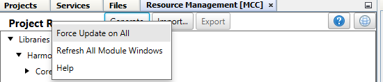
Step2: Enable force update option and press Generate.