10.3.1 SPI Client Mode
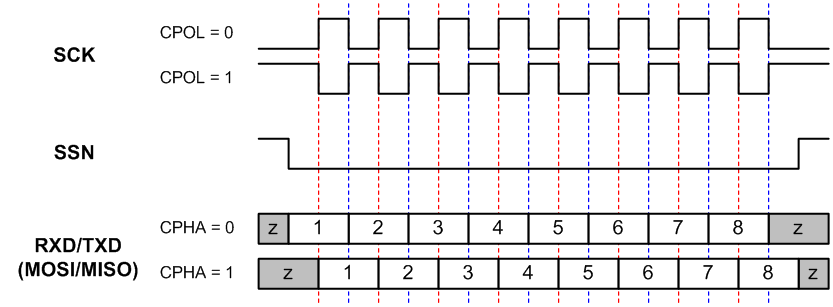
The SPI Client interface supports four standard modes as determined by the Clock Polarity (CPOL) and Clock Phase (CPHA) settings. These modes are given in the following table and figure. In the following figure, the red lines correspond to Clock Phase = 0 and the blue lines correspond to Clock Phase = 1.
| Mode | CPOL | CPHA |
|---|---|---|
| 0 | 0 | 0 |
| 1 | 0 | 1 |
| 2 | 1 | 0 |
| 3 | 1 | 1(1) |
Note:
- The ATWILC3000-MR110xA firmware uses “SPI MODE 0” to communicate with the host.