
1.5 Fabric X-Y Coordinates
(Ask a Question)Each 4-input LUT, D-type flip-flop, carry chain, LSRAM, μSRAM, and Math block has individual X-Y coordinates. For manual placement of these blocks, it is possible to set region constraints using these coordinates. The coordinates are measured from the lower left (0, 0) to the top right corner (X, Y); where X, Y values vary for each device. For more details, see SmartTime User Guide, I/O Editor User Guide, and ChipPlanner User Guide on Libero SoC Design Resources page.
The following figure shows the available X-Y coordinates of LSRAM, μSRAM, and Math block for placement constraints for the PolarFire MPF300 device.
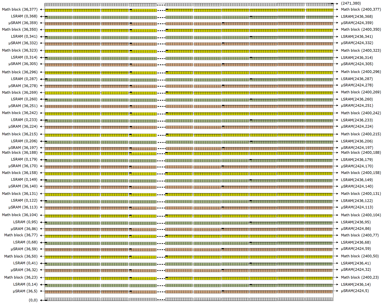
Figure 1-8 shows the available X-Y coordinates of LSRAM, μSRAM, and Math block for placement constraints for the PolarFire SoC MPFS250 device.
To be updated.
The following figure shows the available X-Y coordinates of LSRAM, μSRAM, and Math block for placement constraints for the RT PolarFire RTPF500 device.
To be updated.
The following figure shows the available X-Y coordinates of LSRAM, μSRAM, and Math block for placement constraints for the RT PolarFire SoC RTPFS460 device.
To be updated.