
3 Peripherals
3.1 User LED
There is one user-controllable LED available on the Multi-Phase Power Board. The LED is red and can be activated by pulling the connected I/O line low.
|  |
3.2 User Switch
The Multi-Phase Power Board features a push-button switch, which pulls the connected I/O line low when pressed.
|  |
3.3 User Potentiometer
There is a 10 kΩ potentiometer on the Multi-Phase Power Board. It is connected as a voltage divider and supplies a linearly adjustable voltage to the Adapter connector.
|  |
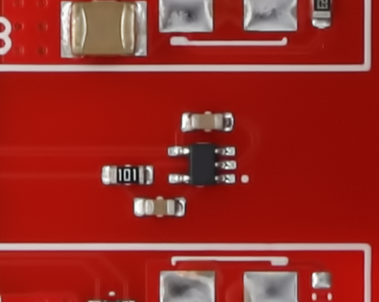
3.4 Temperature Sensor
An MCP9701 analog temperature sensor is located in the power stage of the Multi-Phase Power Board, close to the phase connector. The output voltage is a linear function of the measured temperature:
|  |
3.5 Hall Sensor Header
The Hall sensor connector is a 5-pin 100-mil header for connecting push-pull or open-drain hall sensors. Pull-up resistors set idle signals to 5V, while level shifters adjust the hall signals to 3.3V for the Adapter connector. | 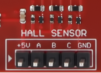 |
| Position on Hall Sensor Connector | Silk Screen Marking | Position on Adapter Connector |
|---|---|---|
| 1 | +5V | – |
| 2 | A | 36 |
| 3 | B | 34 |
| 4 | C | 32 |
| 5 | GND | – |
3.6 PWM Input Header
The PWM input header is a 3-pin 100-mil header with a pinout compatible with standard hobby servos. A pull-up resistor sets the idle signal to 5V, while a level shifter adjusts the PWM signal to 3.3V for the Adapter connector. A 6.8Ω resistor between the +5V pin and the on-board +5V regulator acts as protection against accidental short circuits. | 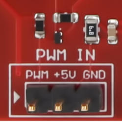 |
| Position on PWM In Connector | Silk Screen Marking | Position on Adapter Connector |
|---|---|---|
| 1 | PWM | 18 |
| 2 | +5V | – |
| 3 | GND | – |