1 Overview

1.1 Ecosystem Overview

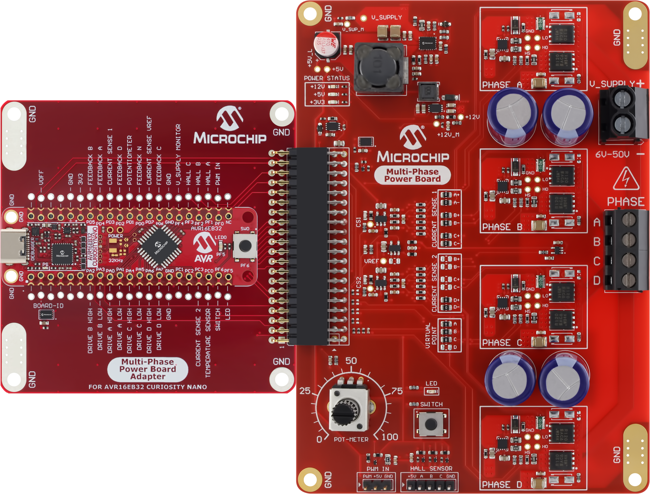
The Multi-Phase Power Board (MPPB) features a modular design and relies on adapter boards to produce the necessary drive signals, enabling the evaluation of various configurations.

Figure 1-1 shows an example setup of the following products connected for a complete motor control solution:
Figure 1-1. A Complete System: Multi-Phase Power Board with Adapter Board and Curiosity Nano

1.2 MPPB Overview

Figure 1-2. Multi-Phase Power Board Overview
V_SUPPLY+5VPower Status LEDs+3V3+12VAdapter ConnectorCurrent Sense Amplifier 1Voltage ReferenceCurrent Sense Amplifier 2Virtual Neutral PointUser PotentiometerUser LEDUser SwitchPWM Input HeaderHall Sensor HeaderPhase OutputPhase OutputPhase OutputPhase OutputTemperature SensorPhase Output

1.3 MPPB Feature List

  • Power stage for motor control
  • Board-to-board connector for Multi-Phase Power Board Adapters
  • Wide voltage range
    • Supports 6-50V external power input
    • Rated for 10A at 24V
  • Four output phases
    • Individually controllable
    • MIC4605 half-bridge MOSFET driver
    • Voltage feedback from each phase
  • User-configurable virtual point
  • Two current sense channels
    • User-configurable phase selection
    • Using MCP6021 Operational amplifiers
  • On-Board Peripherals
    • MCP9701 temperature sensor
    • Potentiometer
    • User LED and push button
    • Optional external PWM input
    • Optional HALL sensor input
  • Board identification in MPLAB® X IDE
  • On-board Power Supplies
    • MIC28512 5V 2A Synchronous buck regulator, steps down input voltage
    • MCP1754 3.3V 150 mA LDO to power connected adapter, peripherals and I/O
    • MCP1661 12V 200 mA PWM Boost Regulator powering the MOSFET drivers