On some device families, the MVIO module features a configurable Low-Voltage detection
(LVD) circuit that can be used to monitor the VDDIOx supply voltage core-independently
using a dedicated interrupt flag. In addition to the interrupt flag, some device families provide a
status bit that can also be used to determine when VDDIOx has dropped below the specified
voltage level. The MVIO LVD trip point is fully configurable for each VDDIOx voltage
domain available. For each device family, there is a complete list of the available trip points in
the electrical specifications section of the respective data sheet.
Important: By default, the MVIO module has hysteresis implemented for the VDDIOx
LVD trip point circuitry that can optionally be disabled. However, it is important to note that this
will slightly affect the trip point values since the hysteresis is no longer applied. Refer to the
electrical specifications section of the device data sheet for more information.
The MVIO LVD trip points were designed around some of the most widely used voltage
regulators based on their associated tolerances, the most common types of batteries, and their
associated cut-off voltages. The VDDIOx Low-Voltage detection circuit can help determine
when a battery or regulated voltage supply being provided to any of the MVIO domains has dropped to
a low enough level to cause concern or require attention in an application.
The MVIO module will remain active and functional as long as VDDIOx supply
pin(s) meet the minimum voltage requirements specified in the device data sheet. The LVD detection
circuitry provides a buffer that potentially allows users to take corrective action when the MVIO
supply voltages have dropped below the ordinarily expected range of operation before the supply
voltages drop so low that the MVIO module stops working and transitions to a Power-on Reset state
until the minimum required supply voltage has been restored.
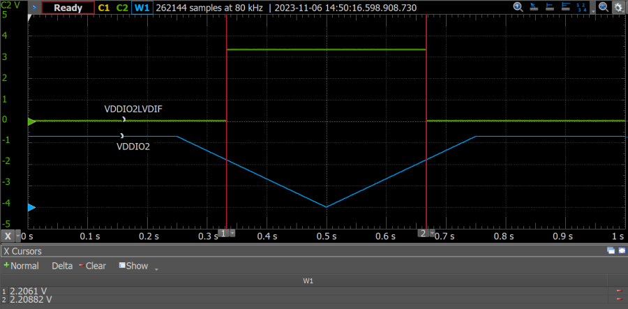
Figure 4-2 illustrates how the VDDIOx
Low-Voltage Detect monitor works on the PIC18-Q24 device family. For this specific example, the
VDDIO2 supply voltage was ramped up and down between 0V and 3.3V, and the
VDDIO2 LVD trip point was configured as 2.20V using the LVD bits of the VDDIO2CON
register. The VDDIO2 LVD interrupt flag (VDDIO2LVDIF) gets set when the VDDIO2
supply voltage drops below the configured LVD threshold and gets cleared in hardware once the supply
voltage has been restored and is above the configured LVD trip point. This feature is not available
on all devices that have MVIO, and its implementation and functionality may also vary from device to
device. For more information, refer to the "Multi-Voltage I/O" chapter of the appropriate
device data sheet.Figure 4-2. VDDIOx Low-Voltage Detect Monitor
Example on PIC18-Q24 Device Family
The online versions of the documents are provided as a courtesy. Verify all content and data in the device’s PDF documentation found on the device product page.