4.3 VDDIOx Voltage Measurement using the Analog-to-Digital Converter
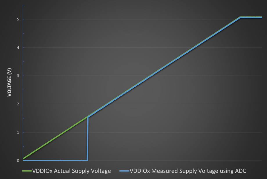
The VDDIOx supply voltage on PIC and AVR devices with MVIO can be measured using the on-chip ADC module. The VDDIOx supply voltage is always divided by a factor of ten, and then provided as an internal input channel to the ADC. Since the MVIO voltage domains are meant to operate independently of VDD and one another, there are instances where it is possible the VDDIOx voltage may be higher than any of the available ADC positive reference voltages. The MVIO supply voltages are divided down to ensure that they are always within the measurable range of the ADC.
The MVIO supply voltage can only be measured using the dedicated ADC channel when the respective VDDIOx voltage domain has met the minimum voltage requirements for operation, and is ready to use as indicated by the associated interrupt flag or status bit. Refer to VDDIOx Ready Voltage Monitor for more information. To measure the MVIO supply voltages using the ADC on PIC devices, "VDDIOx/10" must be selected as the internal ADC channel by writing the appropriate value to the ADC Positive Channel Selection (ADPCH) register. On AVR devices with MVIO, this is done by writing the specified value to the MUX Selection for Positive ADC Input (MUXPOS) register to select the "VDDIO2DIV10" option.

