
4.6 Extension Header Area
The marked area on the grid I7 to R8 can be used for strapping in an Xplained Pro extension header or a 10-pin legacy Xplained/RZ600 header.
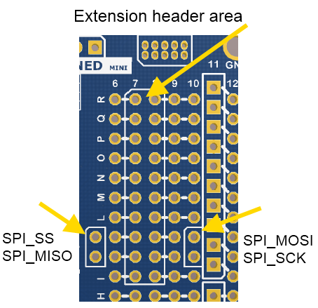
The SPI bus signals are available close to the header at row J and K, enabling easy connection to header pin 15 to 18.
Using pins 11 to 20 enables connection of the 10-pin legacy header used on the RZ600 wireless modules and the 10-pin Xplained sensor modules.
The general bus connections for an Xplained Pro Extension board are indicated in the table below. Detailed wiring can be found in the selected extension board documentation.
| Pin | Signal Name | Signal Description |
|---|---|---|
| 1 | ID | Communication line to the ID chip on the Xplained extension board |
| 2 | GND | Ground |
| 3 | ADC(+) | Analog-to-Digital converter, alternatively positive part of differential ADC |
| 4 | ADC(-) | Analog-to-Digital converter, alternatively negative part of differential ADC |
| 5 | GPIO1 | General purpose I/O |
| 6 | GPIO2 | General purpose I/O |
| 7 | PWM(+) | Pulse-Width Modulation, alternatively positive part of differential PWM |
| 8 | PWM(-) | Pulse-Width Modulation, alternatively negative part of differential PWM |
| 9 | IRQ/GPIO | Interrupt request line and/or general purpose I/O |
| 10 | SPI_SS_B/ GPIO | Slave B select for SPI and/or general purpose I/O |
| 11 | I2C_SDA | Data line for I2C interface |
| 12 | I2C_SCL | Clock line for I2C interface |
| 13 | UART_RX | Receiver line of ATmega168PB USART |
| 14 | UART_TX | Transmitter line of ATmega168PB USART |
| 15 | SPI_SS_A | Slave A select for SPI |
| 16 | SPI_MOSI | Master out slave in line of serial peripheral interface |
| 17 | SPI_MISO | Master in slave out line of serial peripheral interface |
| 18 | SPI_SCK | Clock for serial peripheral interface |
| 19 | GND | Ground |
| 20 | VCC | Power for extension board |