2.2 Data and Design Flows
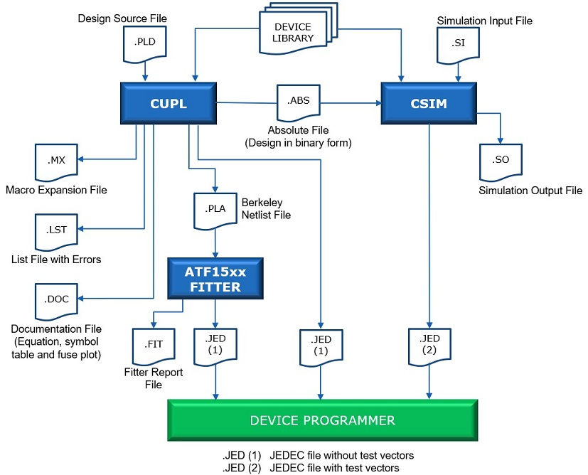
Figure 2-2 illustrates the data flow for creating a design and implementing the design using CUPL.
First, a logic description is created using the CUPL language manually with the WinCUPL II source editor.
Then, the design is compiled to create a fusemap file for downloading to a device programmer. Optionally, a test specification file may be created to verify the design. The CSIM functional simulator is executed to compare the expected values in the test file to the actual values in the absolute file created by CUPL. When the simulation is completed without any errors, the verified test vectors can be appended to the download JEDEC file generated by CUPL.
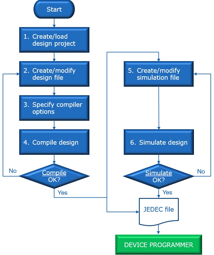
The CUPL design flow via WinCUPL II is described below:
- Create or load project file - To create a new project, click on the New Project shortcut button in the main WinCUPL II window to launch the New Project Wizard. In the New Project Wizard, select the target device type, device package type and device option. A new project file with the extension .WCP will be created, and it will contain all the project related information. To load an existing project, click on the Open Project shortcut button in the main WinCUPL II window and then select the project file (.WCP) that you would like to load into WinCUPL II. After creating or loading a design project into WinCUPL II, the target device type, package type or device option can be changed under the Device Selection tab.
- Create or modify design file - Click on the New/Edit button under Design File Manager to open a new or existing CUPL design file (.PLD) in the WinCUPL II text editor. After entering the logic equations into the CUPL design file, save the file and close the text editor to return to the main WinCUPL II window.
- Specify compiler options - Select the desired compiler options under the Compiler Options tab.
- Compile design - Click on the COMPILE button under Design Compilation to compile the CUPL design. The messages generated by the compiler will be displayed in the Message pane of the main WinCUPL II window, as well as in the LOG file.
- Create or modify simulation file - Click on the New/Edit button under Simulation File Manager to open a new or existing CUPL simulation input file (.SI) in the WinCUPL II text editor. After entering the simulation inputs into the simulation input file, save the file and close the text editor to return to the main window.
- Simulate design - Click on the SIMULATE button under Design Simulation to simulate the CUPL design. The outputs of the simulation will be contained in the simulation output file (.SO).