
3.2.3 SDADC Conversion Polling Mode Application on SAMC21N Xplained Pro Evaluation Kit
Description
This application demonstrates SDADC Conversion in Polling mode. The application uses internal bandgap reference as the input voltage source.
Modules/Technology Used
- Peripheral Modules
- SDADC
- SUPC
- EVSYS
- SERCOM(USART)
Hardware Used
Software/Tools Used
This project has been verified to work with the following versions of software tools:
Refer Project Manifest present in harmony-manifest-success.yml under the project folder firmware/src/config/default.
- Refer the Release Notes to know the MPLAB X IDE and MCC Plugin version.
- Any Serial Terminal application, such as Tera Term terminal application.
Because Microchip regularly updates tools, occasionally issue(s) could be discovered while using the newer versions of the tools. If the project does not seem to work and version incompatibility is suspected. It is recommended to double-check and use the same versions that the project was tested with. To download original version of MPLAB Harmony v3 packages, refer to document How to Use the MPLAB Harmony v3 Project Manifest Feature (DS90003305).
Setup
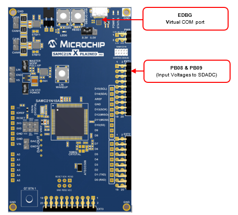
- Ensure that both the positive (INP) and negative (INN) pins on SAMC21N Xplained Pro Evaluation Kit are connected to a voltage source.
- The SAMC21N Xplained Pro Evaluation
Kit allows using the Embedded Debugger (EDBG) for debugging. Connect the Type-A male
to micro-B USB cable to micro-B DEBUG USB port to power and debug the SAMC21N Xplained
Pro Evaluation Kit.
Programming Hex File
The pre-built hex file can be programmed by following the below steps.
- Open MPLAB X IDE
- Close all existing projects in IDE, if any project is opened.
- Go to File -> Import -> Hex/ELF File.
- In the Import Image File
window,
- Create Prebuilt Project,
- Click the Browse button to select the prebuilt hex file.
- Select Device as ATSAMC21N18A.
- Ensure the proper tool is selected under Hardware Tool and click on Next button.
- Select Project Name and Folder,
- Select appropriate project name and folder and click on Finish button
- Create Prebuilt Project,
- In MPLAB X IDE, click on Make and Program Device button to program the device.
- Follow the steps in Running the Demo section below.
Programming/Debugging Application Project
- Open the project (sdadc_conversion_interrupt\firmware\sam_c21n_xpro.X) in MPLAB X IDE
- Ensure SAM C21n Xplained Pro is selected as hardware tool to program/debug the application
- Build the code and program the device by clicking on the Make and Program button in MPLAB X IDE tool bar
- Follow the steps in Running the Demo section below
Running the Demo
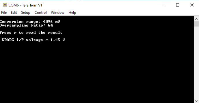
- Open the Tera Term terminal application on the PC (from the Windows Start menu by pressing the Start button).
- Change the baud rate to 115200.
- SDADC is configured to use the internal VREF and the range is set to 4.096V full scale and the default setting of OSR is 64.
- Pressing the ‘r’ key will read
the result and display it, in a form scaled to mV.
Comments
- Reference Application Note: Using Sigma-Delta Analog-to-Digital Converter on SAMC MCU with MPLAB Harmony v3 (DS00003589).
- Reference Training Module: Getting Started with Harmony v3 Peripheral Libraries on SAMC2x MCUs.
- This application demo builds and works
out of box by following the instructions above in Running the Demo section. If
the user needs to enhance/customize this application demo, should use the MPLAB
Harmony v3 Software framework. Refer links below to setup and build the applications
using MPLAB Harmony.
- How to Setup MPLAB Harmony v3 Software Development Framework (DS90003232).
- How to Build an Application by Adding a New PLIB, Driver, or Middleware to an Existing MPLAB Harmony v3 Project (DS90003253).
- Video - How to Set up the Tools Required to Get Started with MPLAB® Harmony v3 and MCC
- Create a new MPLAB Harmony v3 project using MCC
- Update and Configure an Existing MHC-based MPLAB Harmony v3 Project to MCC-based Project