4.3.1 Programming with the DediProg SF600
The recommended method of programming the SPI NOR Flash chips on the EV42J24A is to use a DediProg SF600 level in-system programmer. This programmer connects directly via ribbon cable to the 2x6 header on the EV42J24A. There are two programming headers on the board, and each header has access to two SPI chips. The DediProg software is then used to program the memory devices. The assertion of the correct chip select is controlled by the software, so there is no need to manually redirect the chip select line. Each header is connected to two SPI NOR Flash chips and are independent of each other.
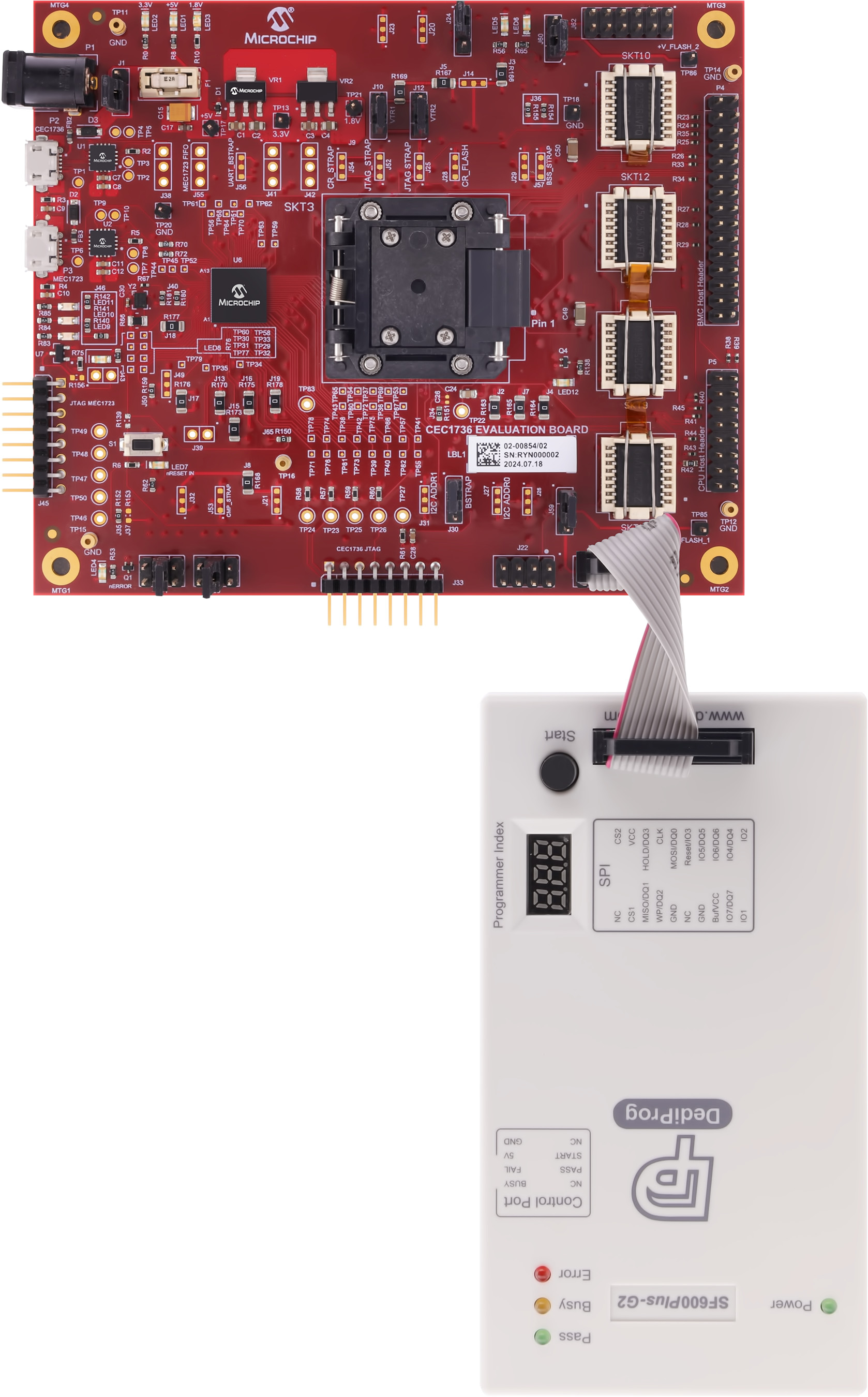
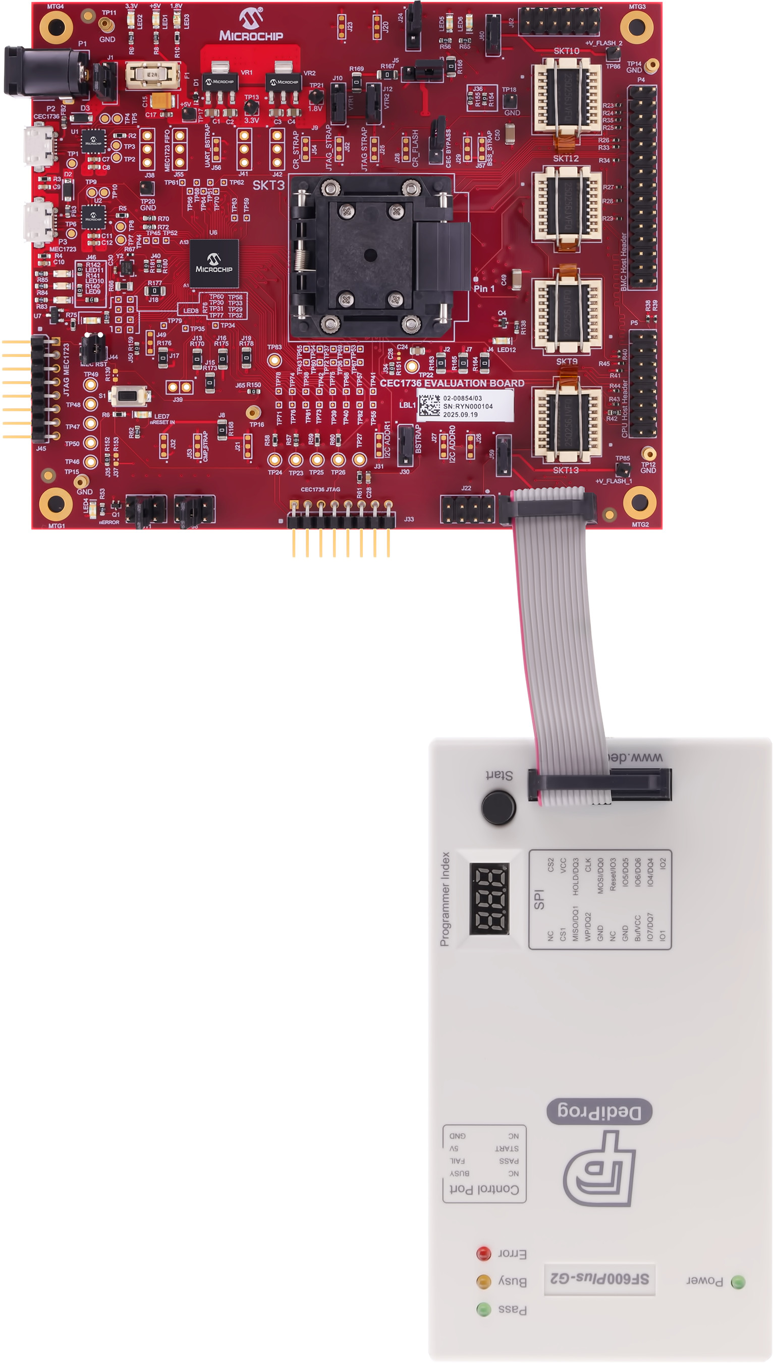
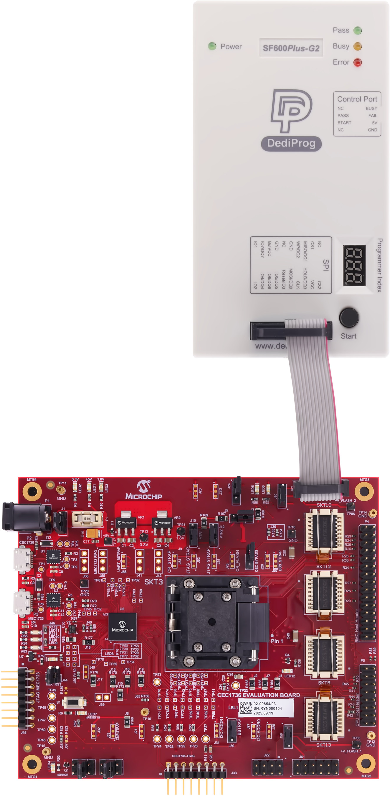
To program the SPI chips, first power on the development board by connecting USB cables to P2 and P3. Make sure the jumper at J1 is set to draw power from the USB cables and that the board is powered on. Connect the DediProg header to one of the programming headers. The photographs below illustrate the connection between the board and the programmer, which varies depending on the board revision and connector type. Pay close attention to the orientation of the pin 1 markers on both the programming cable and the board connector.
| J61 - R2 Connection | J61 - R3 Connection | J62 - R2 or R3 Connection |
|---|---|---|
 |
 |
 |