
4.1.1 MCC SMPS Library Configuration for Open Loop
The following instructions show how to setup the peripherals of the CIP Hybrid Power Starter Kit to be able to operate in Open Loop test mode.
- Open MPLAB X. Connect the CIP Hybrid Power Starter Kit to the computer through an on-board debugger USB port using a conventional micro-USB cable. MPLAB X will detect the CIP Hybrid Power Starter Kit and an Xplained Window appears that provides relevant information about the board.
- Create new Standalone Project in
MPLAB X. Select the PIC16F1779 device. Select the CIP Hybrid Starter Kit as
programming tool. Name this project “OpenLoop”.
Figure 4-2. Creating New MPLAB X Standalone Embedded Project 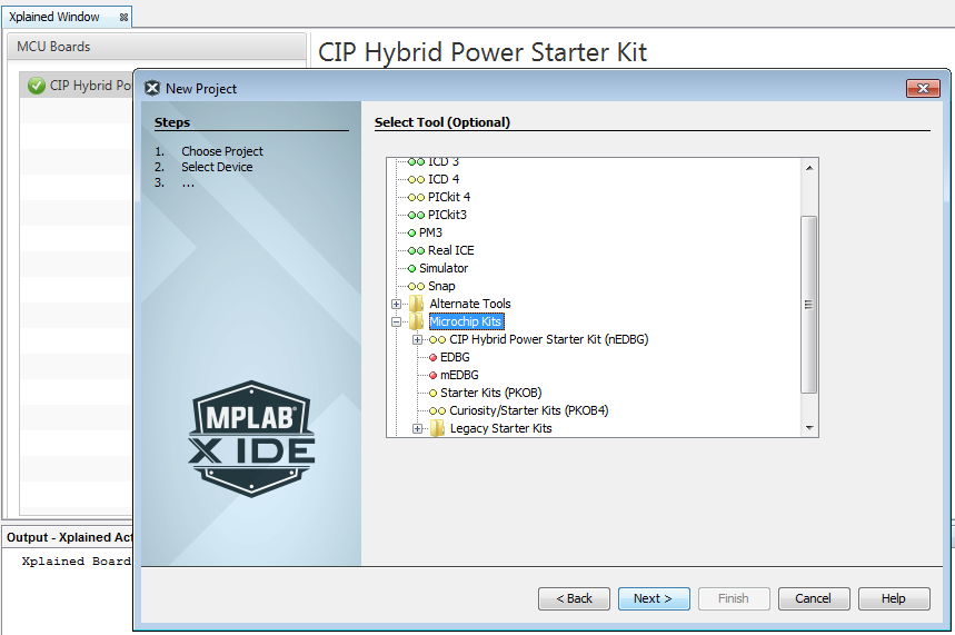
- Open MCC. Save the MCC configuration
as
OpenLoop.mc3. - Change the internal oscillator clock
to 8 MHz from the System Module in the Project Resources area. On the Pin Manager,
change the package to QFN44.
Figure 4-3. System Module Settings - Go to the Device Resources area,
click SMPS Power Controllers and expand CIP Blocks, double click on
ModulatorBlockPCMC. This action will move the selected module to the
Project Resources area.
Figure 4-4. ModulatorBlockPCMC 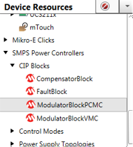
- In the Project Resources area, click
the ModulatorBlockPCMC. On the Configuration tab, under Hardware
Settings, select Half-Bridge mode. Change the switching frequency to 500 kHz, and
the duty cycle to 20%. Check Standalone Open Loop PWM.
Figure 4-5. Hardware Settings for Open Loop - Under the Complementary Output
Generator Settings, change rising dead time to 50 ns, falling dead time to 40 ns,
and blanking time to 250 ns.
Figure 4-6. Complementary Output Generator Settings for Open Loop 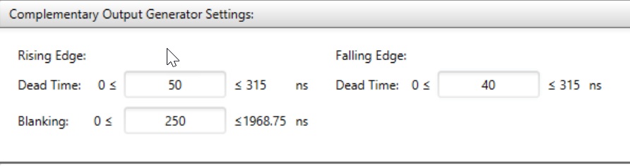
- Select COG4 and PWM11 in the
Sub-Module Selection and click the Upload button. Check if COG4 and PWM11
have been correctly added to the Project Resources area.
Figure 4-7. Sub-Module Selection for Open Loop 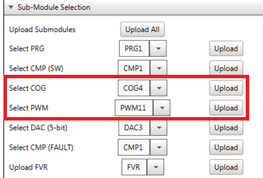
- Go to the Pin Manager: Grid View.
Search for the Modulator section. Select RD5 as the output pin for signal OUT_H and
RD4 as the output pin for signal OUT_L.
Figure 4-8. Pin Manager Selection for Open Loop - Click the Generate button from Project Resources area to generate the code.
- Program the PIC16F1779 device on the
CIP Hybrid Power Starter Kit by clicking the “Make and Program Device Main Project”
icon.
Figure 4-9. Generating Code Button and Programming - Alternatively, the user can also
download the Open Loop firmware to the CIP Hybrid Power Starter Kit by dragging the
generated
.hexfile of the project to the CURIOSITY drive. The.hexfile is located on the --dist\default\production folder.Figure 4-10. Drag and Drop Method for Programming the Device - The CIP Hybrid Power Starter Kit can now be tested for Open Loop operation and will immediately start to generate the PWM output signals driving the synchronous buck converter.