
6.7 Tamper Detection and Tamper Responses
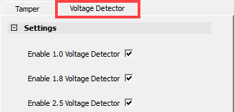
(Ask a Question)A tamper macro is provided in the Libero software catalog to access tamper flags and response inputs from fabric. There are two sets of input/output ports in a tamper macro. One set corresponds to the tamper detection flags and the tamper responses. Other set corresponds to the user voltage detectors, which triggers an alarm when the supply voltage falls below a minimum level or raises above a maximum level.
The following figure shows the PF_TAMPER macro and its configurable options for the PolarFire FPGA.

The following figure shows the PFSOC_TAMPER macro and its configurable options for the PolarFire SoC FPGA.


Important: Enable eNVM POR Digest Check is only applicable for the PolarFire SoC FPGA.
The following table lists the tamper macro ports.
| Port | Direction | Description |
|---|---|---|
| CLEAR[31:0] | Input | Assertion of these signals clear the associated tamper flags (FLAGS[31:0]). |
| IO_DISABLE | Input | Disables all the user I/O (or non-dedicated) pins when this signal is asserted. All the output buffers are tri-stated (any configured pull-up or pull-down is still honored) and the input buffers are disabled. |
| SECURITY_LOCKDOWN | Input | When asserted, it forces all the access control locks active and clears all the security unlocks that might be set. It puts the device in lockdown state. |
| RESET_DEVICE | Input | This is equivalent to asserting the device reset pin. The user design is immediately powered down and the device re-executes its initialization sequence. This pin should not be connected directly to I/O pad, the PLL lock output or the designs system reset as it puts the system controller in reset. See PolarFire FPGA: How to Perform On-Demand Digest Check Application Note for usage of this port. |
| ZEROIZE | Input | Assertion of this signal initiates zeroization process. See Zeroization. |
| VOLT_DETECT_2P5_HIGH_CLEAR | Input | Assertion of this signal clears the VOLT_DETECT_2P5_HIGH tamper flag. |
| VOLT_DETECT_2P5_LOW_CLEAR | Input | Assertion of this signal clears the VOLT_DETECT_2P5_LOW tamper flag. |
| VOLT_DETECT_1P8_HIGH_CLEAR | Input | Assertion of this signal clears the VOLT_DETECT_1P8_HIGH tamper flag. |
| VOLT_DETECT_1P8_LOW_CLEAR | Input | Assertion of this signal clears the VOLT_DETECT_1P8_LOW tamper flag. |
| VOLT_DETECT_1P0_HIGH_CLEAR | Input | Assertion of this signal clears the VOLT_DETECT_1P0_HIGH tamper flag. |
| VOLT_DETECT_1P0_LOW_CLEAR | Input | Assertion of this signal clears the VOLT_DETECT_1P0_LOW tamper flag. |
| CLK_FROM_RCOSC_160MHz | Input | Clock for latches when Latch System Controller outputs option is enabled. Must be connected to internal 160 MHz RC oscillator. |
| FLAGS[31:0] | Output | Tamper detection flags to the fabric. These are cleared by asserting CLEAR[31:0] signals or the device reset. See Tamper Detection Flags. |
| RESET_REASON[4:0] | Output | Indicates the source of last system reset, see Reset Reason. |
| SLOW_CLOCK | Output | The flag is asserted when the system controller clock is slowed down to 20 MHz. When the VDD brownout is detected, the system controller's clock automatically reduces from 80 MHz to 20 MHz. There is no automatic shutdown of the device due to detection of brownout in operational mode, but an alarm signal (slow_clock) is asserted to the fabric so that the user may take action if desired. User may observe few pulses on this signal before it settles to high. The system controller's clock switches to 80 MHz if voltage recovers without going below the reset threshold. |
| VOLT_DETECT_2P5_HIGH | Output | When asserted, it indicates that the VDD25 (2.5V) supply is above the maximum threshold voltage level. |
| VOLT_DETECT_2P5_LOW | Output | When asserted, it indicates that the VDD25 (2.5V) supply is above the minimum threshold voltage level. In other words, when it indicates low, the supply is below the minimum threshold voltage level. |
| VOLT_DETECT_1P8_HIGH | Output | When asserted, it indicates that the VDD18 (1.8V) supply is above the maximum threshold voltage level. |
| VOLT_DETECT_1P8_LOW | Output | When asserted, it indicates that the VDD18 (1.8V) supply is above the minimum threshold voltage level. In other words, when it indicates low, the supply is below the minimum threshold voltage level. |
| VOLT_DETECT_1P0_HIGH | Output | When asserted, it indicates that the VDD (1.0V) supply is above the maximum threshold voltage level. |
| VOLT_DETECT_1P0_LOW | Output | When asserted, it indicates that the VDD (1.0V) supply is above the minimum threshold voltage level. In other words, when it indicates low, the supply is below the minimum threshold voltage level. |