
4.2.3 Power the Board
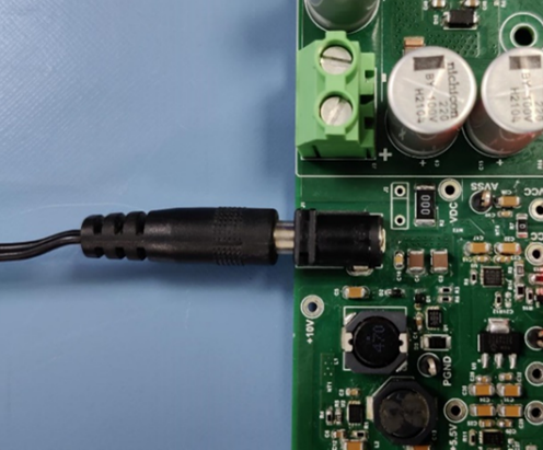
Plug the 24V power supply into connector J1 on the MCLV-48V-300W Inverter Board.
Important: Before powering on the system, verify that all
connections are properly secured and correctly configured.
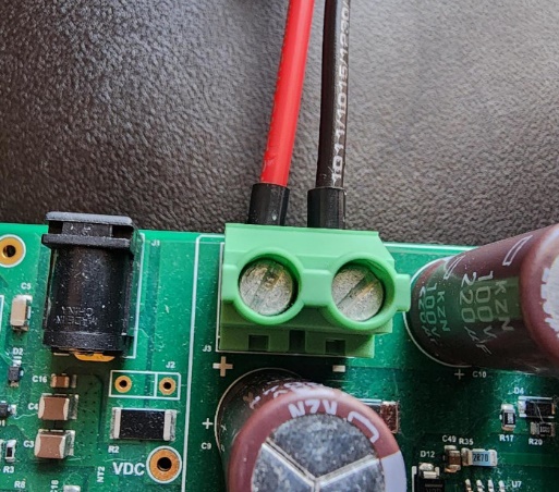
Important: Be aware J1 and J3 are the same node, unless
separated by removing the R2 resistor. Refer to the “Motor Control Low-Voltage
48V-300W Inverter Board User’s Guide” (DS50003297) for more details.