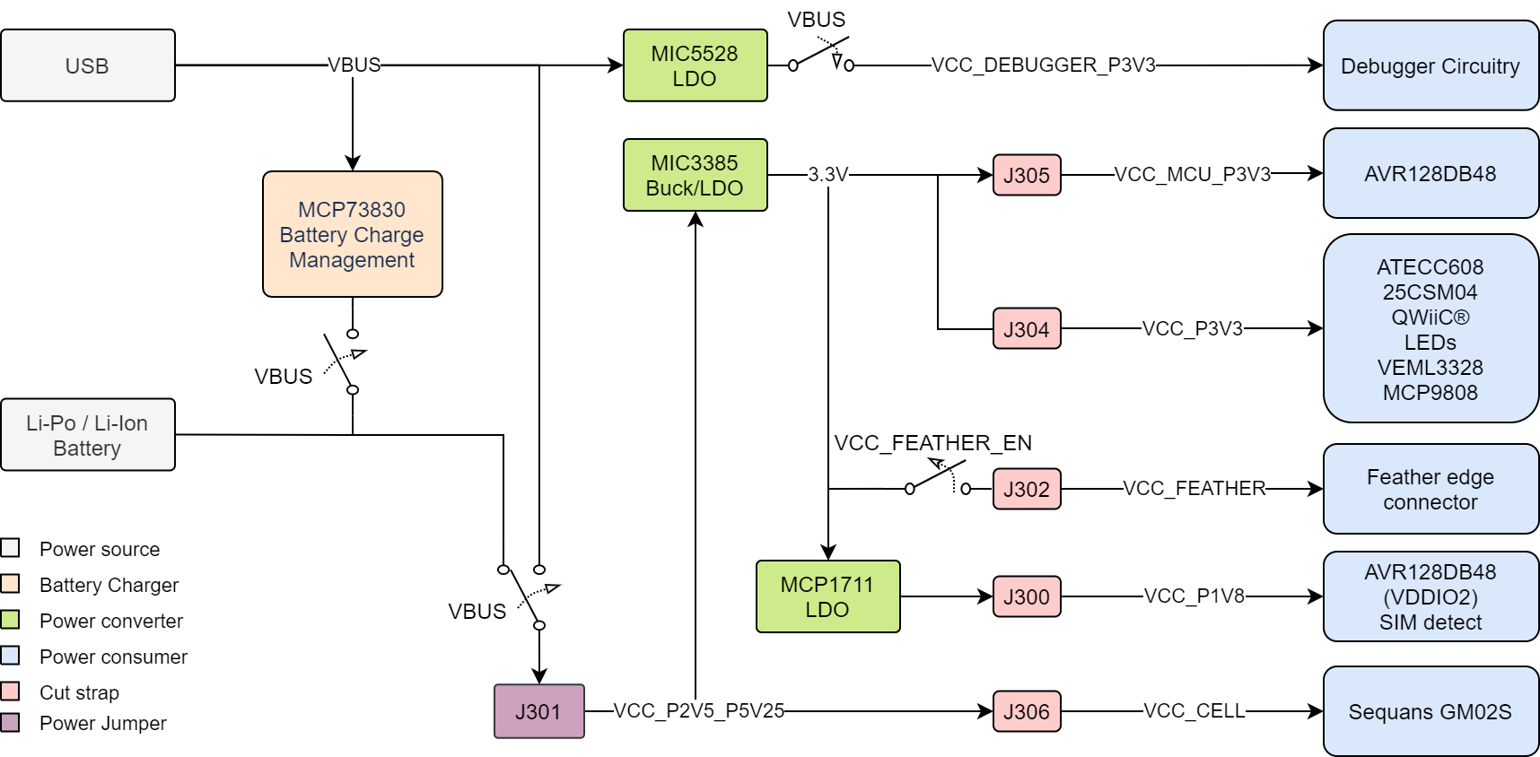
The board can be powered through the USB port, a Li-Ion/LiPo battery, or by an external
power source. The board contains one buck converter for 3.3V with LDO standby mode and
one LDO for 1.8V. The debugger is supplied from its own LDO and will only be powered
when the board is connected to USB power. The Sequans GM02S
module is powered directly from the input power and generates a 1.8V output
voltage.
Info: The maximum available current from
the USB is limited to 500 mA. The current is shared between charging the battery (if
connected) and the system.
Important: When not powered from a USB, it is
important to leave the AVR128DB48 pins connected to the CDC UART in
Tri-State (Input) mode to prevent the debugger from getting powered through its
GPIO.
The power supply is designed with four power switches (MIC94165) to prevent leakage when powered by a battery. All
three switches are open when not connected to USB power, disabling battery charging and
the on-board debugger. The Feather edge connector is powered-on by default.Figure 3-1. Power Supply Block
Diagram
Warning: Any external
power applied to the board must be in the range of 2.5–5.25V. Any voltage Exceeding
5.25V may damage the board.
When the board is supplied by a battery, the only limitation regarding current is caused
by the voltage regulators. The maximum output current from the two regulators, MIC3385
and MCP1711, is listed in the table below.
Table 3-1. Output Current Limit
Regulator
Output Current Limit [mA]
MCP1711
150
MIC3385 (PWM)
900
MIC3385 (LDO)
120
The online versions of the documents are provided as a courtesy. Verify all content and data in the device’s PDF documentation found on the device product page.