
6.1 Example Application with PoDL
The example application uses five nodes with the same hardware on each node. The PoDL power circuit is provided by the add-on board shown earlier.
The following eye diagram measurements were done on the TRXN and TRXP pins of a LAN8651. These measurements were done for each combination of transmitter and receiver (i.e. Node 0 transmits and Node 4 receives, Node 0 receives and Node 4 transmits). The resulting eye diagram matrix is shown below in Figure 6-6.
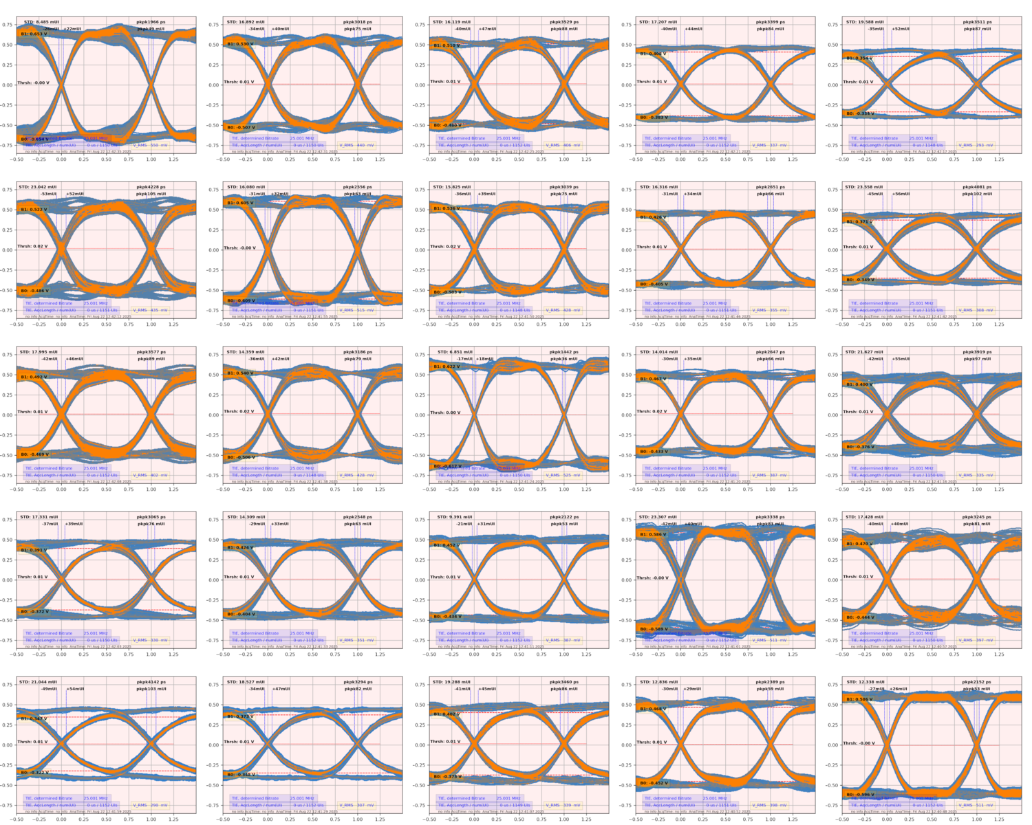
It is clearly visible that the worst case scenario for this mixing segment is when Node 0 transmits and Node 4 receives, or vice-versa. In either case, a jitter of about 2 ns exists on timing of signals with a maximum eye-opening of about 402 mV and a signal noise of about 5.0 mV.