23.2.1 POR and Voltage Monitors
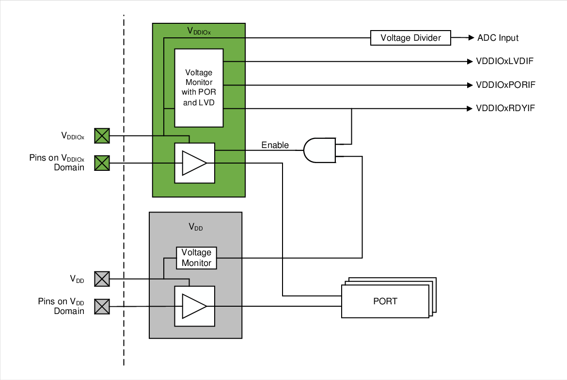
Each voltage domain has its own dedicated POR circuit to monitor the supply voltage level. The POR circuit is automatically enabled on supply power-up and holds the corresponding voltage domain logic in reset state until the power supply has reached sufficient voltage for the corresponding voltage domain logic to operate properly. Once this supply voltage is reached, the POR circuit on that voltage domain will power itself down to save power and re-arm itself if the supply voltage drops too low. For VDD power domain, the device’s main POR circuit is used whereas for VDDIOx domain, a separate POR circuit is included in the MVIO domain. The POR and PORVDDIOx bits in the PCON0 and PCON1 registers are used to represent when the corresponding voltage domain has recovered from a POR reset as well as the corresponding system level interrupt VDDIOxPORIF.
Once the voltage domain logic is released by the POR circuit, it is important to ensure that the VDDIOx voltage domains are powered up and operating at sufficient voltage for the level shifters to work properly. To achieve this, the MVIO module has an integrated voltage monitor for each VDDIOx power domain powered using the respective VDDIOx supply. This voltage monitor is used to indicate when the MVIO voltage level thresholds have been achieved in order for the internal voltage level shifters to operate safely and correctly. The system level interrupt VDDIOxRDYIF is used to indicate when the corresponding VDDIOx voltage domain is not active and ready to use.
Refer to Figure 23-1 for more information about the different voltage monitoring features of the MVIO module. Additionally, refer to the Power Sequencing section for different ways to power up both voltage domains.

