4 Board Calibration
The Solar Battery LED Streetlight board is pre-calibrated for the voltage and current input ranges appropriate for each board variant. If the solar input range is increased or decreased for the application, or the battery configuration is changed, the voltage dividers and current monitoring resistors can be adjusted to fully utilize the ADC range of the controller. An Excel-based design tool, included in the download package available at www.microchip.com, contains the calculations for these resistor values.
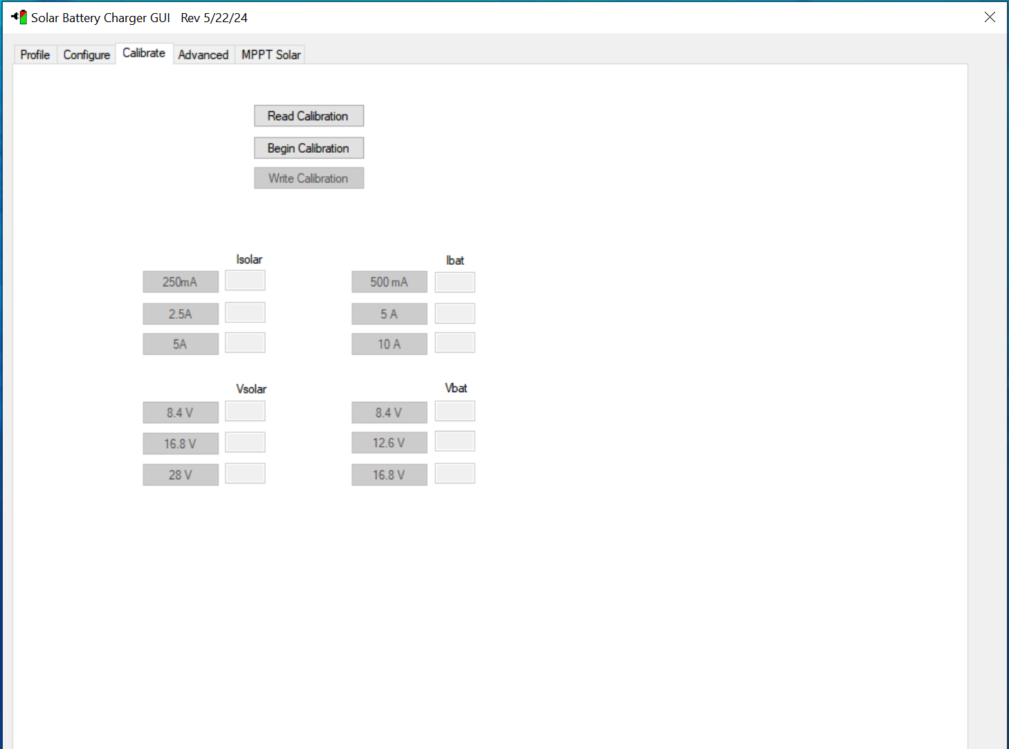
In production, each board (or at least each board variant/revision) will need to be calibrated using a precision voltage and current source capable of representing the input and output voltage range of the end product. More information can be found in Productizing the Design.