1 Interrupt Latency Measurement
Figure 1-1 shows the top-level block diagram for Interrupt latency measurement. The Expose Interrupt ports to Fabric option in the PolarFire SoC MSS configurator > Misc tab and the Use Master interface option in the PolarFire SoC MSS configurator > Fabric Interface Controllers tab are enabled. The Global or Local interrupt that is generated from the fabric interrupt_gen.v is connected to MSS F2M interrupt lines. The application running on the U54_1 processor clears the interrupt by writing to the fabric register using the FIC3 interface.
Interrupt lines used are MSS_INT_F2M0 and MSS_INT_F2M1. The common interrupt vector is used for global and local interrupts. The source of the interrupt is verified in the handle_trap function of mpfs_hal by reading mcause Control and Status Register (CSR).

The following table lists the fabric logic address map for generating Local and Global interrupts.
| FIC3 Address | Data | Operation |
|---|---|---|
| 0x40000000 | 0x1 | Generates the local interrupt |
| 0x40000000 | 0x0 | Clears the interrupt |
| 0x40000000 | 0x2 | Generates the global interrupt |
| 0x40000000 | 0x0 | Clears the interrupt |
Implementation
The MSS_INT_F2M0 port is used for the local interrupt and MSS_INT_F2M1 port is used for the Global interrupt. Both these interrupts are mapped to the U54_1 application core. The FIC3 is used for interfacing with the fabric interrupt generation logic. The MMUART port is enabled for serial communication.
See Table 1-1 for generating Local and Global interrupts.
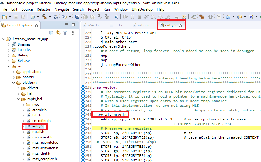
For measuring the interrupt latency, the hardware performance monitoring CSR “mcycle” is read before asserting an interrupt. The mcycle CSR is again read as soon as the interrupts enter the trap vector function, as shown in Figure 1-2. The time difference between mcycle read values are used to measure the interrupt latency.