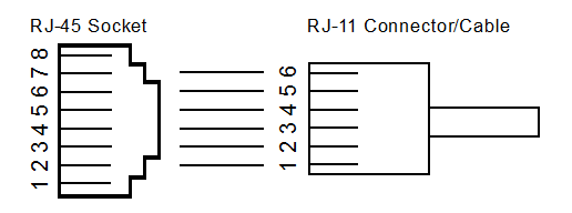
9.3.1 Connecting an RJ-11 Type Cable to an RJ-45 Jack on the Debugger
The MPLAB ICD 4 In-Circuit Debugger has an RJ-45 connector for communication to the target. Connect the RJ-11 type cable into the RJ-45 connector by simply inserting it into the center of the RJ-45 connector.
Refer to the figure below for the pinouts for this connection.

| Pin | RJ-45 | Function | Pin | RJ-11 |
|---|---|---|---|---|
| 1 | TMS | EJTAG Test Mode Select | ||
| 2 | Reserved | |||
| 3 | PGC (ICSPCLK) | Standard Com Clock/TCK (JTAG Test Clock) | 2 | PGC (ICSPCLK) |
| 4 | PGD (ICSPDAT) | Standard Com Data/TDO (JTAG Test Data Output) | 3 | PGD (ICSPDAT) |
| 5 | GND | Ground | 4 | GND |
| 6 | VDD_TGT | Power on target | 5 | VDD_TGT |
| 7 | VPP | Power | 6 | VPP |
| 8 | TDI | JTAG Test Data Input |
