The ADC module hardware is equipped with post-conversion computation features. These features provide post-processing functions such as digital filtering/averaging and threshold comparison. Based on computation results, the module can be configured to take additional samples or stop conversions and an interrupt may be asserted.
Figure 1. Computational Features Simplified Block Diagram
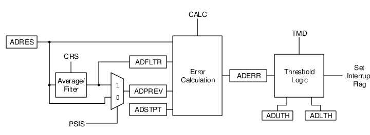
The operation of the ADC computational features
is controlled by the MD bits.
The module can be operated in one of five modes:
- Basic:
This is a Legacy mode. In this mode, ADC conversion occurs on single (DSEN =
0) or double (DSEN =1) samples. ADIF is set after each conversion is complete. ADCHxIF is set according to the Calculation mode. - Accumulate: With each trigger, the ADC conversion result is added to the accumulator and ADCNT increments. ADIF is set after each conversion. ADCHxIF is set according to the Calculation mode.
- Average: With each trigger, the ADC conversion result is added to the accumulator. When the RPT number of samples have been accumulated, a threshold test is performed. Upon the next trigger, the accumulator is cleared. For the subsequent tests, additional RPT samples are required to be accumulated.
- Burst Average: At the trigger, the accumulator is cleared. The ADC conversion results are then collected repetitively until RPT samples are accumulated and finally the threshold is tested.
- Low-Pass Filter (LPF): With each trigger, the ADC conversion result is sent through a filter. When RPT samples have occurred, a threshold test is performed. Every trigger after that, the ADC conversion result is sent through the filter and another threshold test is performed.
The five modes are summarized in the following table.
| Mode | MD | Register Clear Event | Value after Cycle(1) Completion | Threshold Operations | Value at ADCHmIF Interrupt | |||||
|---|---|---|---|---|---|---|---|---|---|---|
| ADACC and CNT | ADACC | ADCNT | Retrigger | Threshold Test | Interrupt | AOV | ADFLTR | ADCNT | ||
| Basic | 0 | ACLR = 1 |
Unchanged | Unchanged | No | Every Sample | If threshold=true | N/A | N/A | count |
| Accumulate | 1 | ACLR = 1 |
S1 + ADACC or (S2-S1)(2) + ADACC | If (ADCNT = 0xFF): ADCNT,
otherwise: ADCNT+1 |
No | Every Sample | If threshold=true | ADACC Overflow | ADACC/2CRS | count |
| Average | 2 | ACLR = 1 or ADCNT ≥ ADRPT at GO set or retrigger |
S1 + ADACC or (S2-S1) + ADACC | If (ADCNT = 0xFF): ADCNT,
otherwise: ADCNT+1 |
No | If ADCNT ≥ ADRPT | If threshold=true | ADACC Overflow | ADACC/2CRS | count |
| Burst Average | 3 | ACLR = 1 or at GO set or retrigger |
Each repetition: same as Average End with sum of all samples | Each repetition: same as Average End with ADCNT = ADRPT | Repeat while ADCNT < ADRPT | If ADCNT ≥ ADRPT | If threshold=true | ADACC Overflow | ADACC/2CRS | ADRPT |
| Low-pass Filter | 4 | ACLR = 1 |
S1 + ADACC-ADACC/ 2CRS or (S2-S1) + ADACC-ADACC/2CRS | If (ADCNT = 0xFF): ADCNT,
otherwise: ADCNT+1 |
No | If ADCNT ≥ ADRPT | If threshold=true | ADACC Overflow | ADACC/2CRS (Filtered Value) | count |
|
Notes:
|
||||||||||