7.4 Functional Description
The bootloader loads the program from an external host to the internal memory of the PL460. The external host can access the instruction memory, data memory and registers through SPI. The bootloader only works in SPI Mode 0 (CPHA=1 and CPOL=0). The basic data transfer is:
The basic frame sent from the host through the MOSI signal is composed as shown in the following table:
| Address | Command | Data |
|---|---|---|
| 32-bit block | 16-bit block | n blocks of 32 bits |
All the blocks in the basic frame sent by MOSI use little-endian format.
Each frame received from the host will be acknowledged with a 32-bit signature through the MISO signal.
There is a series of SPI commands supported by the bootloader. The commands are:
| Command | Description | addr(31:0) | data(n*32-1:0) |
|---|---|---|---|
| 0x0000 | Write word on one address | 0xAAAAAAAA(1) | 0xDDDDDDDD(2) |
| 0x0001 | Write words on consecutive addresses | 0xAAAAAAAA(1) | 0xDDD…DDD(2) (3) |
| 0x0002 | Read words on consecutive addresses | 0xAAAAAAAA(1) | 0x000…000(4) |
| 0x0003 | Read word on one address | 0xAAAAAAAA(1) | 0x00000000 |
| 0x0004 | Write number of decryption packets | 0x00000000 | 0x0000DDDD(2) |
| 0x0005 | Write decryption initial vector | 0x00000000 | 0xDDD…DDD(2) (3) |
| 0x0006 | Write decryption signature | 0x00000000 | 0xDDD…DDD(2) (3) |
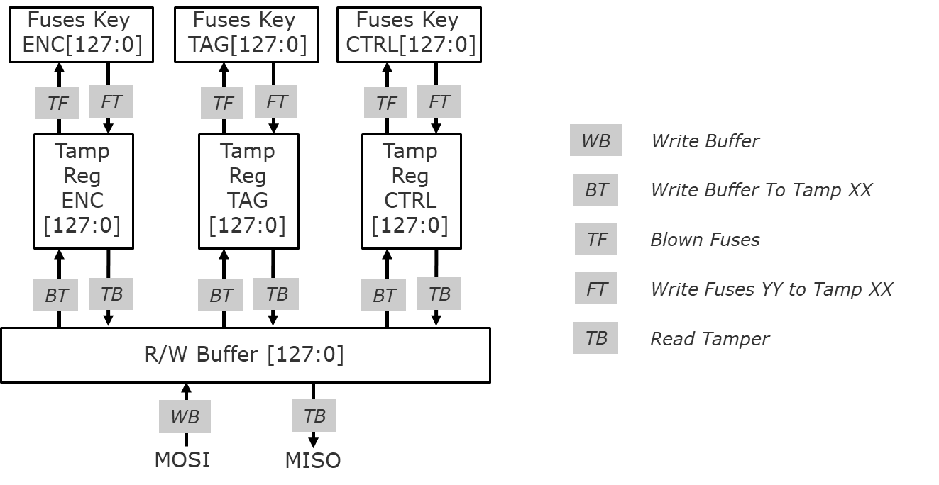
| 0x0007 | Write 128 bit fuses value to Buffer register | 0x00000000 | 0xDDD…DDD(2) (3) |
| 0x0008 | Write Buffer register to Tamper register for KEY_ENC_FUSES | 0x00000000 | 0x00000000 |
| 0x0009 | Write Buffer register to Tamper register for KEY_TAG_FUSES | 0x00000000 | 0x00000000 |
| 0x000B | Write Buffer register to Tamper register for CONTROL_FUSES | 0x00000000 | 0x00000000 |
| 0x000C | Blow desired fuses | 0x00000000 | 0x00000000 |
| 0x000D | Write KEY_ENC_FUSES to the corresponding Tamper register | 0x00000000 | 0x00000000 |
| 0x000E | Write KEY_TAG_FUSES to the corresponding Tamper register | 0x00000000 | 0x00000000 |
| 0x0010 | Write CONTROL_FUSES to the corresponding Tamper register | 0x00000000 | 0x00000000 |
| 0x0011 | Read Tamper register | 0x00000000 | 0x000…000(4) |
| 0x0012 | Read bootloader status | 0x00000000 | 0x00000000 |
| 0x0013 | Start Decryption | 0x00000000 | 0x00000000 |
| 0x0014 | Start/Stop BOOTLOADER access window in Host mode | 0x00000000 | 0x00000000 |
| 0x0015 | Start Decryption Plus | 0x00000000 | 0x00000000 |
| 0xA55A | Control of MISO signal transferred to M7-SPI | 0x00000000 | 0x00000000 |
| 0xA66A | Control of MISO signal transferred to M7-SPI and Bootloader clock disabled | 0x00000000 | 0x00000000 |
| 0xDE05 | Unblock bootloader | 0x00000000 | 0xDDDDDDDD(2) |
- ‘AA’ is an address byte.
- ‘DD’ is a data byte.
- Command contains as many bytes as needed to send.
- Command contains as many ‘00’s as bytes wanted to be read.
The figure below shows the structure of the registers and data transfers for fuses and their control logic.

