
3 Running the Demo
(Ask a Question)This section describes how to run the DRI demo, check the results on the board, and observe the frequency on an oscilloscope.
To run the demo, setup the PolarFire Evaluation board as explained in Run PROGRAM Action. This programs the evaluation kit with DRI design and ensures that all DIP switches of SW11 are ON. Execute the following tests:
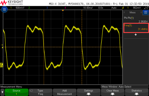
TEST 1: Switch OFF SW11 DIP1 and change it back to ON to configure the transceiver in 1.25G at 31.25 MHz of TX and RX Clock frequency.
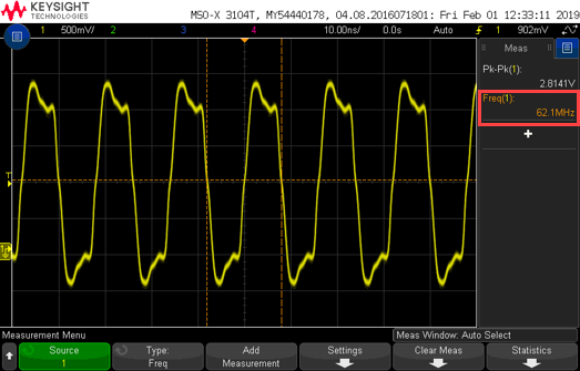
TEST 2: Switch OFF SW11 DIP2 and change it back to ON to configure the transceiver in 2.5G mode at 62.5 MHz of TX and RX Clock frequency.
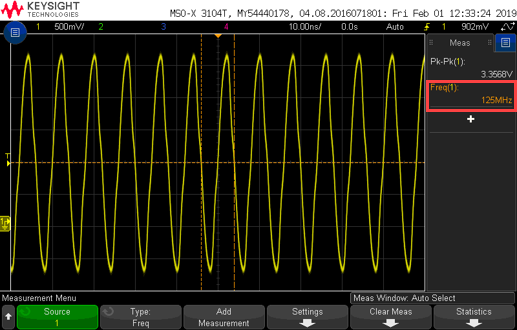
TEST 3: Switch OFF SW11 DIP3 and change it back to ON to configure the transceiver in 5G mode at 125 MHz of TX and RX Clock frequency.
TEST 4: Switch OFF DIP5 and change it back to ON to configure OUT0 and OUT1 frequencies of Dynamic CCC.
TEST 5: Switch OFF DIP6 and change it back to ON to configure OUT2 and OUT3 frequencies of Dynamic CCC.
The following table lists the status of LEDs as per selected inputs.
| Test No. | Input/Output | LED4 | LED5 | LED7 | LED8 | LED9 | LED10 | LED11 |
|---|---|---|---|---|---|---|---|---|
| TX_CLK_STABLE | RX_READY | RX_VAL | Status | |||||
| TEST 1 | DIP1-1.25G | ON | ON | ON | ON | OFF | OFF | OFF |
| TEST 2 | DIP2-2.5G | ON | ON | ON | OFF | ON | OFF | OFF |
| TEST 3 | DIP3-5G | ON | ON | ON | OFF | OFF | ON | OFF |
| TEST 4 | DIP5-CCC OUT0-OUT1 | ON | ON | ON | OFF | OFF | ON | ON |
| TEST 5 | DIP6-CCC OUT2-OUT3 | ON | ON | ON | ON | ON | OFF | OFF |
Probe internal signals of the design from the PolarFire FPGA through test points to get the output frequency. Table 3-2 lists the output signals and probing points to observe the clock changes on an oscilloscope.
| Signal | Header | Probe Test Point |
|---|---|---|
| CC-Out2 | J7 | Pin-4 |
| CC-Out3 | Pin-6 | |
| CC-Out0 | J8 | Pin-5 |
| CC-Out1 | Pin-3 | |
| RX_CLK_R | J8 | Pin-9 |
| TX_CLK_R | J8 | Pin-13 |