
13.1 Functional Description
(Ask a Question)This section describes the implementation details of the Sequence Controller.
The following figure shows the block diagram of Sequence Controller.
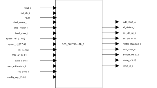
The start_motor_i and stop_motor_i signals are used to trigger motor starting and stopping operations. The speed_ref_i input is the motor reference speed, while the speed_cl_i input is the threshold motor speed at which the cl_status_o is asserted. This signal is asserted as long as the reference speed is equal to or above the threshold speed. The vq_i input is the Iq PI output, and is used in checking for rotor lock condition. If a rotor lock is detected, the motor is restarted from zero speed. The number of times the motor is restarted before entering Fault state is specified by the max_ar_i state. The calib_done_i signal must be asserted (level high), when predetermined ADC samples have been accumulated for offset computation.
The pwm_midmatch_i signal is an active-high-pulse of one system clock cycle width, which is asserted periodically at the rate of the PWM frequency. The foc_done_i signal must be asserted (active-high-pulse with one system clock cycle delay) when all the FOC loop computations are complete. The adc_start_o provides the start conversion pulse (rising edge) for an ADC interface block. The en_idq_pi_o signal is used to enable the current PI controller(s). The en_pwm_o is used to enable the PWM generation block. The motor stopped_o signal (level high) is used to clear accumulators or buffers in the design. The sensor_reset_o signal is used to reset and initiate sensor calibration.