
3 Introduction
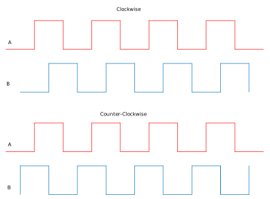
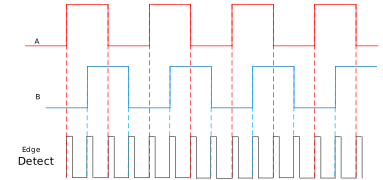
(Ask a Question)Incremental encoder is the most common sensor used for Field Oriented Control (FOC) of Permanent Magnet Brush Less DC (BLDC) or Permanent-Magnet Synchronous Motor (PMSM). This sensor gives relative angular position as the output in the form of pulses. A quadrature encoder, typically produces two outputs, which have pulses phase shifted by 90°, as shown in Figure 3-1. The phase shift between the two signals A and B represents the direction of rotation. The encoder interface logic uses edge detection on rising edge and falling edge of A and B, as shown in Figure 3-2. This gives a resolution that is four times the encoder resolution and produces a very high resolution from a low cost encoder.
The following figure shows the encoder signals in clockwise and counter-clockwise directions.
The following figure shows the edge detection of encoder pulses for higher resolution.
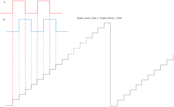
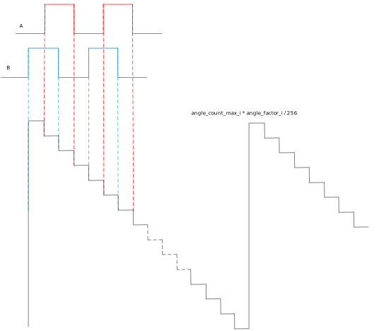
After the edge detection, counters are used to get a rotor angular position in terms of an electrical angle so that, it can be directly used for FOC. The Angle_count_max value represents the total number of edges that will be detected in one mechanical rotation of the rotor. The angle output ranges from 0 to 262143, where 262143 represents 360°. The variation of angle output with respect to the edges is shown in Figure 3-3 for positive speed and Figure 3-4 for negative speed. The speed output is calculated based on the rate of change of angular position.
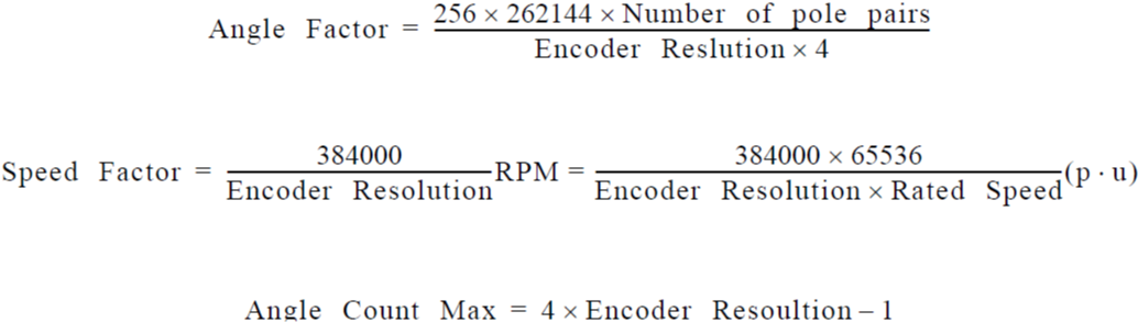
Three parameters are used to configure the encoder interface:
The following figure shows the Theta output for the positive direction.
The following figure shows the Theta output for the negative direction.
Summary
(Ask a Question)The following table provides a summary of the Encoder Interface IP characteristics.
| Core Version | This document applies to Encoder Interface v4.2. |
| Supported Device Families |
|
| Supported Tool Flow | Requires Libero® SoC v11.8 or later releases. |
| Licensing | Complete encrypted RTL code is provided for the core, enabling the core to be instantiated with SmartDesign. Simulation, Synthesis, and Layout can be performed with Libero software. Encoder Interface is licensed with encrypted RTL that must be purchased separately. For more information, see Encoder Interface. |
Features
(Ask a Question)Encoder Interface has the following key features:
- Computes the relative angular position
- Computes the filtered speed output
Implementation of IP Core in Libero Design Suite
(Ask a Question)IP core must be installed to the IP Catalog of the Libero® SoC software. This is done automatically through the IP Catalog update function in the Libero SoC software, or the IP core can be manually downloaded from the catalog. Once the IP core is installed in the Libero SoC software IP Catalog, the core can be configured, generated, and instantiated within the SmartDesign tool for inclusion in the Libero project list.