
10.1 Functional Description
(Ask a Question)The following figure shows the block diagram of PWM Scaling.
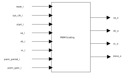
The PWM scaling calculates the scaled phase voltages. The number of clock cycles between the start_i and done_o is 4 x g_NO_MCYCLE_PATH constant. After a computation is triggered, the next start must be triggered only after 4 x g_NO_MCYCLE_PATH clock cycles.
The PWM scaling performs the following functions:
- Scaling of phase voltages according to the
following equation:

- To use the advantage of voltage boost
provided by space vector modulation (SVM), pwm_gain_i can be multiplied by a factor of 1.15
as shown in the following equation:

- Generates PWM with specified PWM frequency.
PWM period that configures the PWM frequency is configured using the following equation:
