
7.1 Functional Description
(Ask a Question)This section describes the implementation details of the T-Format Interface.
The following figure shows the top-level block diagram of the T-Format Interface.
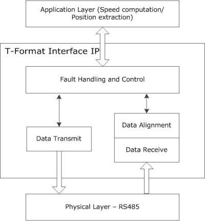
For complete details on T-Format, see Tamagawa datasheets. The following table lists the various commands that are used to request data from the external device and their functions, and the number of data fields returned for each command.
| Command ID | Function | Number of Data Fields in Received Frame |
|---|---|---|
| 0 | Rotor Angle (Data Read) | 3 |
| 1 | Multiturn data (Data Read) | 3 |
| 2 | Encoder ID (Data Read) | 1 |
| 3 | Rotor Angle and Multiturn data (Data Read) | 8 |
| 7 | Reset | 3 |
| 8 | Reset | 3 |
| C | Reset | 3 |
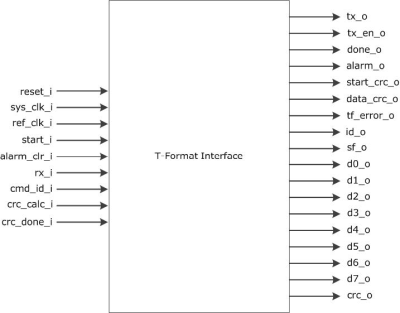
The following figure shows the system-level block diagram of the T-Format Interface.
Thefollowing figure shows the functional block diagram of T-Format interface.
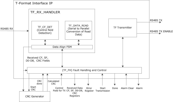
Each communication transaction in T-Format starts with a transmission of Control Frame (CF) from the requestor, followed by a frame received from the external device. The TF Transmitter block generates serial data to be sent to the external device. It also generates an optional tx_en_o signal required by some RS-485 converters. The encoder receives the data transmitted, and transmits a frame of serial data to the IP, which is received in the rx_i input port of the IP block. The TF_CF_DET block first detects the control field and identifies the ID value. The data length is determined based on the received ID value, and subsequent fields are received and stored in respective registers using the TF_DATA_READ block. After the complete data is stored, the data in all fields except the CRC field is sent to an external CRC generator block, and the calculated CRC generated by this block is compared to the CRC received. Someof the other errors are also checked, and the done_o signal is asserted (‘1’ for one sys_clk_i cycle) after every error free transaction.