
5.1 Functional Description
(Ask a Question)This section describes the implementation details of the Hall interface block.
The following figure shows the system level block diagram of the Hall interface.
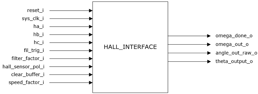
The Hall interface block generates the rotor angle based on three Hall inputs:
- The angle_out_raw_o output is the raw angle generated based on Hall events
- The theta_output_o output is the smoothened interpolated angle
- The hall_sensor_pol_i input is used to indicate, if the Hall signals are active high or active low
The angle generated is used to determine the rotor speed. The clear_buffer_i input is used to clear the speed filter buffer when the motor is stopped. The computed speed is filtered using a filter block. The filter block computation is triggered by the fil_trig_i input and the filter time constant is decided by the filter_factor_i input. The filtered speed is available at omega_out_o output, and the omega_done_o output (pulse of one clock cycle width) indicates the speed is ready for use by the subsequent blocks.