Figure 5-5. External Power Supply and Current Measurement Header
Figure 5-6. WBZ351
Interface (LGA Pads) and QSPI Flash Interface
Figure 5-7. mikroBUS Click
Interface and Crypto IC
Figure 5-8. RGB LED
Figure 5-9. User LED
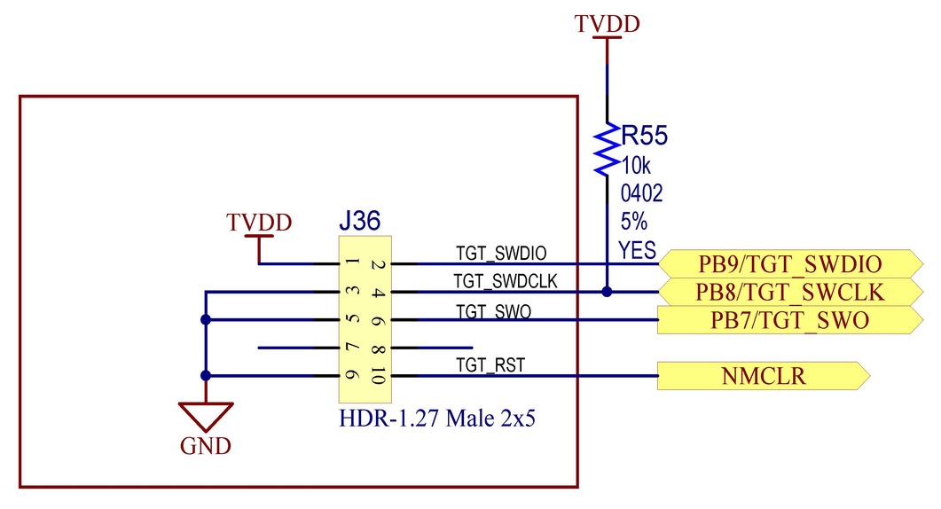
Figure 5-10. Debug Header
Figure 5-11. Xpro Header
Figure 5-12. Temperature Sensor
Figure 5-13. Reset Button
Figure 5-14. User Button 1 (Low Power)
Figure 5-15. User Button 2
Figure 5-16. Application Virtual Comm Port
Figure 5-17. Serial Wire Debug
Figure 5-18. VPP Switch
Figure 5-19. VDD Bleeder
Figure 5-20. USB High Speed Hub
Figure 5-21. MCP2200 USB UART Converter
Figure 5-22. Stitching Cap
Figure 5-23. PKoB4 Main Micro 1 of 2
Figure 5-24. PKoB4 Main Micro 2 of 2
Figure 5-25. PKoB4 Debug Header
Figure 5-26. VDDIN Cap
Figure 5-27. VDDIO Bypass Caps
Figure 5-28. VDDCORE Bypass Caps
The online versions of the documents are provided as a courtesy. Verify all content and data in the device’s PDF documentation found on the device product page.