4.1.2 Generating a OrCAD Capture Schematic Symbol
(Ask a Question)- Invoke Cadence OrCAD Capture CIS. 2. . 3. 4.
- Go to File > New > Library, then select the
*.olbfile. Go to Design > New Part from Spreadsheet... The New Part Creation Spreadsheet dialog appears as shown in the following figure.
In the New Part Creation Spreadsheet dialog, specify the following:
- Part Name
- Number of sections
Part Ref Prefix - choose Alphabetic
Figure 4-4. New Part Creation Spreadsheet Dialog 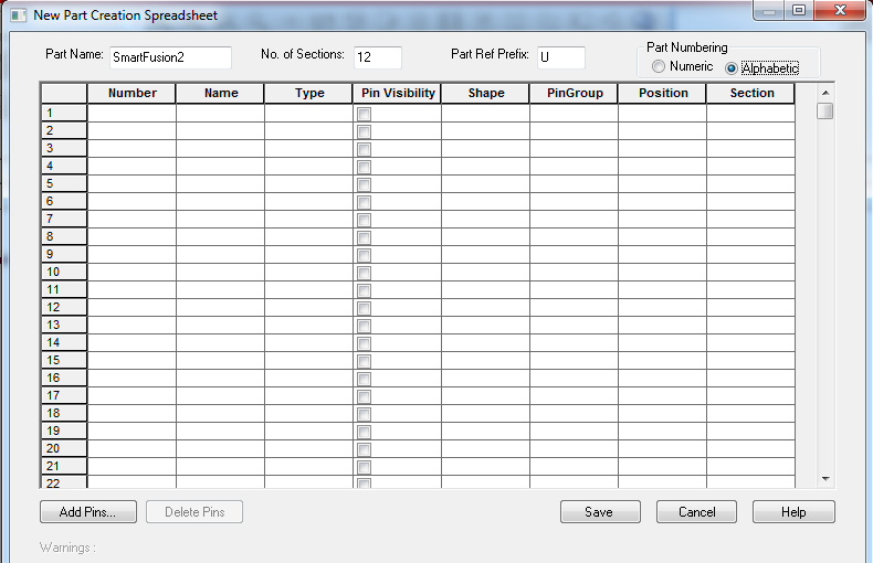
- From the Example PAT Spreadsheet, select and copy all the cells,
excluding the column headers as shown in the following figure.
Figure 4-5. Example PAT Spreadsheet - Final Stage 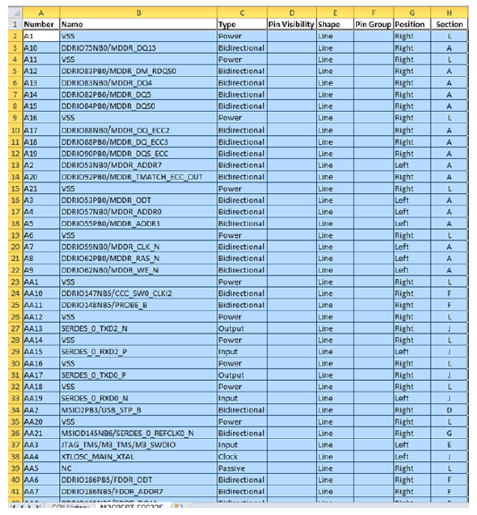
Select the top left cell of New Part Creation Spreadsheet dialog and paste the copied data. Check if all the columns match between the Example PAT Spreadsheet and New Part Creation Spreadsheet dialog as shown in the following figure.
Important: In the Pin Visibility column, select all the check boxes. Some of the check boxes for the power pins might not be selected. If you want those pins to be visible, ensure that they are selected.Figure 4-6. New Part Creation Spreadsheet Dialog with Data 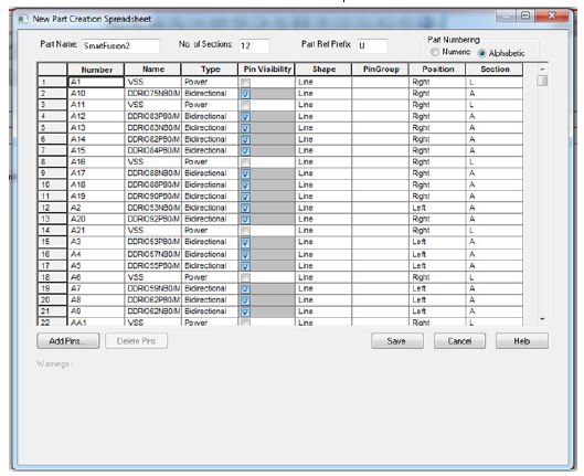
- Click SaveImportant: When you click save, the Design Rule Check (DRC) operation is triggered. If there are any errors reported during the DRC, modify the Example PAT Spreadsheet to fix those errors. If there are just warnings and if you want to ignore them, click Continue to proceed with generating the Part..
Figure 4-7. New Part Created in the Library 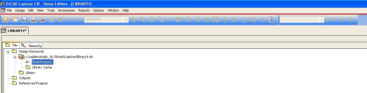
Double-click the part that is created to display the first section as shown in the following figure.
Figure 4-8. Schematic Symbol - First Section 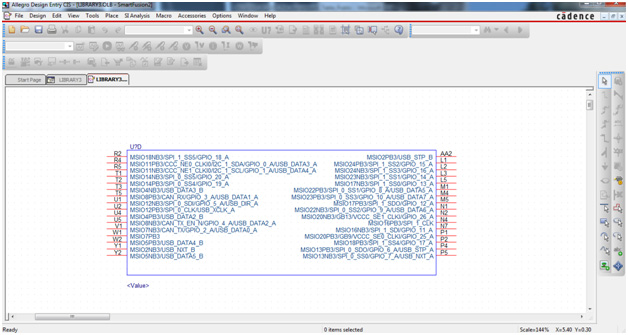
You can navigate to all the sections that are created.
- To go to the next part, go to View > Next Part or press Ctrl + N.
- To go to the previous part, go to View > Previous Part or press Ctrl + B.
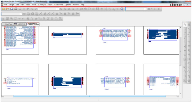
To see all the blocks of the schematic symbol, go to View > Package.
The schematic symbol is ready to use. The following figure shows all the blocks of the schematic symbol that are generated from the Example PAT spreadsheet.
Figure 4-9. Package View of the Schematic Symbol