
1.8 usb_headset
This topic provides instructions and information about the MPLAB Harmony 3 USB Speaker Basic demonstration application, which is included in the MPLAB Harmony Library distribution.
Description
This demonstration application configures the development board to implement a USB Headset device configured to run at 48 kHz sampling rate at 16 bit per sample.
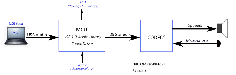
The USB Device driver in Full Speed mode will interface to a USB Host (such as a personal computer) via the USB Device Stack using the V1.0 Audio Function Driver. The embedded system will enumerate with a USB audio device endpoint and enable the host system to input/output audio from the USB port using a standard USB Full-Speed implementation. The embedded system will stream USB playback audio to the Codec. The Codec Driver sets up the audio interface, timing, DMA channels and buffer queue to enable a continuous audio stream. The digital audio is transmitted to the codec through an I2S data module for playback and record through a headphone jack.
Architecture
The application runs on the PIC32 MZ EF Curiosity 2 (MZEFC2) demo board, as follows:
- Processor runs @ 200 MHz
- 4 push buttons (SW1-SW4)
- 3 LEDs (all red LED1-LED3) and RGB LED (LED4).
- AK4954 Codec Daughter Board mounted on X32 socket
- USB Device interface
The usb_headset application uses the MPLAB Code Configurator to setup the USB Audio Device, codec, and other items in order to play back the USB audio through the Codec Module.
A USB Host system is connected to the micro-mini USB device connector. The application detects the cable connection, which can also supply device power; recognizes the type of connection (Full Speed); enumerates its functions with the host, isochronous audio streaming playback and record through device. Audio stream data is buffered in 1 ms frames for playback/record using the AK4954 Codec daughter board. Audio is heard through the Headphone jack (HP OUT). Audio is sent to the record channel from the on-board microphone.
The following figure shows the basic architecture for the demonstration.
Demonstration Features
- Audio playback/record using a AK4954 codec daughter board on the MZEFC2 board.
- USB connection to a host system using the USB Library Device Stack for a USB Headset device using the MZEFC2 boards
- MZEFC2 board button processing for volume/mute control
- USB Attach/Detach and mute status using an LED on MZEFC2 board
- Utilization of the PIC32 I2S peripheral (as host) on the MZEFC2 board
Note that all the calls to the AK4954 codec driver uses the form DRV_CODEC_xxx rather than DRV_AK4954_xxx. This is to make the code more generic, such that another codec could be substituted for another without having to make changes to the application code except for the location of the driver's public header file.
Tools Setup Differences
Harmony MCC Component Blocks
MPLAB-X Harmony 3 projects only have one associated configuration. When each Harmony 3 project is created the MPLAB-X Code Configurator (MCC) will support application driver and library code generation for the selected processor.
Additional, MCC code generation is supported by adding additional components to the project graph. This includes Core peripheral support for the processor device, the Harmony framework, and the board support package.
The USB Headset application will be generated from the following MCC Project Graph after each block's component parameters are configured.
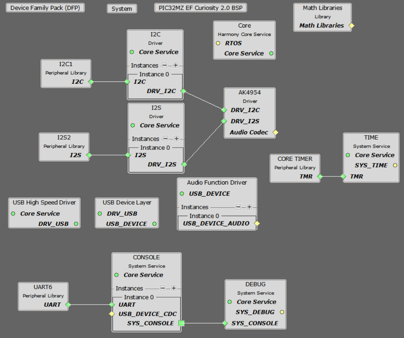
The creation of this Project Graph and the configuring of each components will be described in the following Sections.
Harmony Core Block
Start MCC for the project in order to add the Harmony and the application code components. The Board Support Package (BSP) for the Pic32 MZ EF Curiosity board should be selected first from the Available Components.
Next, the Harmony core is selected without FreeRTOS. Answer Yes to all questions except for the one regarding FreeRTOS; answer No to that one.
USB Audio Component Blocks
The MCC USB Audio Stack component blocks can added by selecting the Libraries/USB/Device Stack/Audio Function Driver component template under the MCC Available Components list, as shown below.
Answer yes to all questions. This allows the generation of the USB High Speed Driver, the USB Device Layer and Audio Function Driver components.
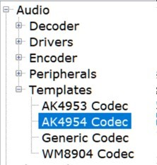
AK4965 Daughter Board Component Blocks
Under Audio\Templates, double-click on AK4954 Codec Template (shown below). Answer Yes to all questions. This loads the AK4954 Codec component along with associated I2C, I2S and timer driver components.
Debug Console Output
Debug output to the console is sent to UART6 using the PKOB4 USB connections as a virtual com port on the PC. This is the same USB connection used to program the device. Three components block have to be added to the diagram: UART6, Console and Debug. These can use the default configuration settings.
Harmony Code Configuration Options
Each block in the MCC Project Graph may need to be configured through parameters for the specific application. These parameters are accessed by selecting the block with the mouse, and appear in the Configuration Options window, where they can be edited. The next section describes the configuration of the USB, Math, and Codec component blocks for the USB Speaker with “Bass Boost” application.
USB Configuration
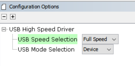
The application uses USB Library as a "Device" stack, which will connect to a "Host". The USB High Speed Driver is set to “Full Speed”, V1.0 interface (not “High Speed”, V2.0 Interface):
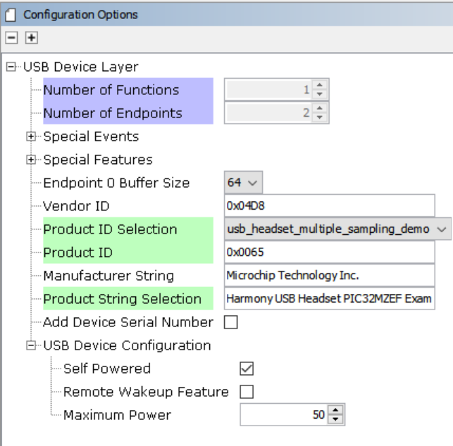
The USB Device Layer is configured by selecting Product ID Selection as “usb_headset_multiple_sampling_demo” with an endpoint buffer size of 64 (bytes). The Product String Selection is changed to “Harmony USB Speaker w/Bass Boost Example”. This information will be used to generate the fullSpeedConfigurationDescriptor array variable structure (located in initialization.c under the config folder) that defines the enumeration of device functions with the USB Host. This structure defines the connection to the host at 48 kHz with 16 bit stereo channel data.
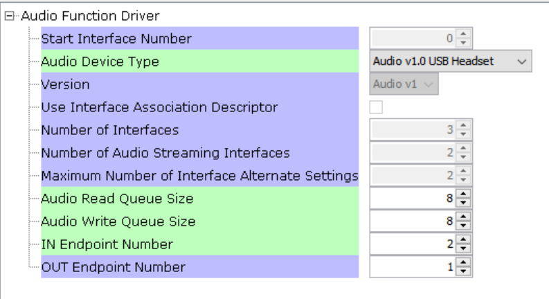
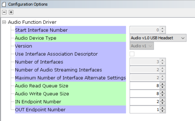
The Audio Function Driver is configured with an Audio Read Queue that matches that of the codec driver write queue for this Audio V1.0 USB Speaker interface.
A playback packet queue of length 8 is set with the Audio Read Queue Size. The Audio Write Queue Size should be the same (8), which should also match the Audio Write Queue Size of the I2S driver. The The maximum USB write packets size is set to 48 * 2 channels/sample * 2 bytes/channel= 192 bytes, which gives a 1ms stereo sample packet size at 48Khz (the standard data frame length at this rate), thus the read buffer size needs to be of the same size. The write buffer size should be half of this (96 bytes), since the 1ms write buffer only contain single channel (mono) audio data at the 48Khz rate at the same bit resolution (16 bit).
The AK4954 Codec
Using the MZEFC2 and the AK4954 Audio Codec Daughter Board:
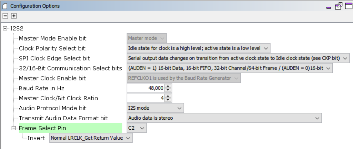
The AK4954 codec uses a I2C interface for configuration and control register setting and SPI interface configured as I2S. The settings are shown below.
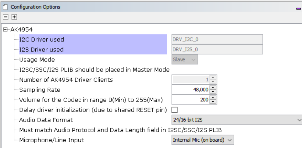
The I2S Driver uses a transfer queue size of 8, which applies to both read and write channels, and matches that that of the USB Read/Write Queue length:
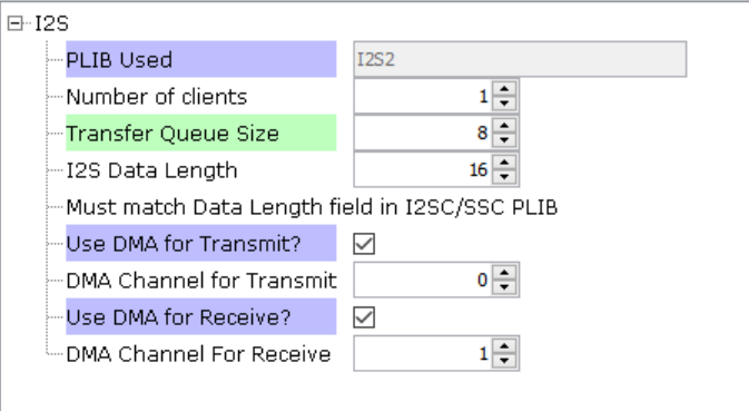
When the I2S2 driver is used for DRV_I2S_0 the codec usage mode automatically changes to “Client”
The I2C blocks can be used without changes to the configuration.
Clock Manager
PIC32 MZ EF PLL Clock
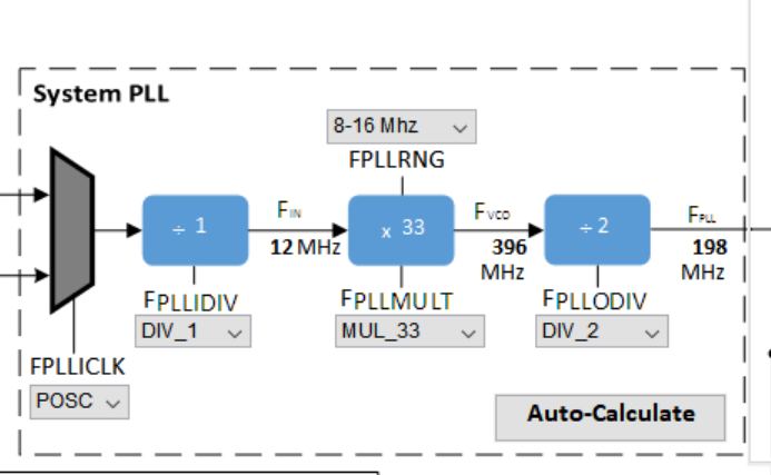
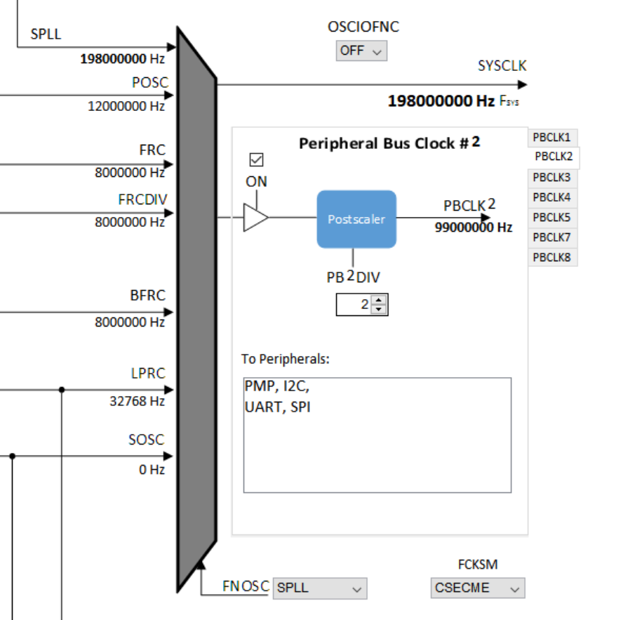
The CPU, Memory and Peripheral clock are generated from the 198Mhz PLL Clock, as configured below.
The I2S clocks are setup for 48KHz sampling rate, with stereo 16 bit samples, giving a 32 bit sample frame. The I2S clocks will be generated, as follows:
| I2S Function | Value | Description |
|---|---|---|
| LRCK | 48.000000 K | Stereo Sample rate clock |
| BCLK | 3072000 Hz | Bit Rate Clock |
| MCLK | 12.288000 MHz | Host Clock |
The clock configuration diagram is shown using Tools/Clock Configuration menu selection. The system clock is 198Mhz, generated from the System PLL, as configured below.
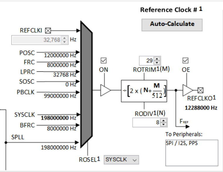
I2SC2 REFCLOCK01 Configuration
The I2S host the MCLK to approximate 12.288Mhz. This is sourced the Reference Clock #1 as shown below.
Harmony Code Generation
All the needed drivers, middleware, libraries and application framework code can be generated from the MCC blocks (MCC components) placed in the MCC Project Graph.
The generated framework code is placed under the firmware/src/config directory under the name of the configuration used for the Harmony 3 project. The initial application code is located in the firmware/src directory app.c and app.h files, which utilize the framework drivers, middleware and library APIs located in definitions.h located in the config directory.
All Harmony applications first execute the SYS_Initialize function, located in initialization.c. This is executed from the main function to initialize various subsystems such as the clock, ports, BSP (board support package), codec, usb, timers, and interrupts. The application APP_Initialize function in app.c is executed last in the generated SYS_Initialize routine after the system initializations have completed.
The SYS_Tasks function (located in tasks.c) is used to update the USB subsystems, WM8904 driver, timers etc., as well as the application state machine (APP_tasks routine in app.c). This function is executed from the main polling loop. The polling loop either execute SYS_Tasks repeatably in the infinite loop to perform the updates, or it the updates occur as separate processes executed at fixed time intervals using an RTOS schedular.
The application utilizes a simple state machine (APP_Tasks executed from SYS_Tasks) with the following functions:
- Setup the drivers and USB Library interface
- Respond to USB Host control commands (“Attach”, “Detach”, “Suspend”)
- Initiate and maintains the bidirectional data audio streaming for the "USB Playback" function.
- Sense Volume control button pushes and set LED status lights
Building the Application
This section identifies the MPLAB X IDE project name and location and lists and describes the available configurations for the demonstration.
Description
The parent folder for these files is audio/apps/usb_headset. To build this project, you must open the audio/apps/usb_headset/firmware/*.X project file in MPLAB X IDE that corresponds to your hardware configuration.
MPLAB X IDE Project Configurations
This table lists and describes the supported configurations of the demonstration, which are located within ./firmware/src/config.
| Project Name | BSP Used | Description |
|---|---|---|
| uh_pic32mz_ef_c2_ ak4954 | pic32_mz_ef_c2 | This demonstration runs on the PIC32 MZ EF Curiosity 2 board with the AK4954 Codec. |
Configuring the Hardware
This section describes how to configure the supported hardware.
Using the PIC32 MZ EF Curiosity 2 and the AK4965 Daughter Board
The PIC32 MZ EF Curiosity board and the AK4954 Audio Codec Daughter Board only requires the AK4954 Codec Daughter board to be connected to X32 Header 2 as shown below. No jumper settings are required.
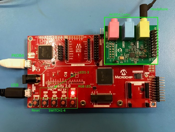
AK4954 Audio Codec Daughter Board on PIC32 MZ EF Curiosity 2 board setup. Headphone Out Jack is green. Microphone In Jack is pink.
Connect headphones to the green HP OUT jack of the Codec Daughter Board (as shown in the Figure above). The onboard microphone (AK4954 Daughter board) will be used for the audio input.
As shown, the PIC32 MZ EF Curiosity will be programmed through the USB cable connected to the PKOB4 micro-mini connector. Program debug can also be performed over USB this connection.
Running the Demonstration
This section demonstrates how to run the demonstration.
Description
Compile and program the target device. While compiling, select the appropriate MPLAB X IDE project. Refer to Building the Application for details
Do the following to run the demonstration:
- Configure the hardware, as described in the previous section, for the selected MPLAB-X project.
- Connect power to the board, compile the application and program the target device. Run the device. The system will be in a waiting for USB to be connected (LED1 off).
- Connect to the USB Host via the micro-mini connector (see Configuring the Hardware).
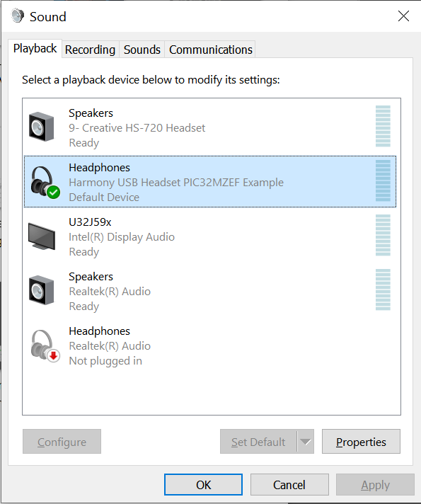
- Allow the Host computer to acknowledge, install drivers (if needed), and enumerate the device. No special software is necessary on the Host side. LED1 will blink after enumeration. It will continue to blink until the Harmony USB Speaker is selected as the speaker device, and the audio stream is started. It will then turn a solid color.
- If needed, configure the Host computer to use the usb_headset as the selected audio recording device. For Windows, this is done in the "Recording" tab in and the "Playback" tab of the "Sound" dialog".
- Open a playback/record application (such as Skype, or Audacity) and initiate playback and record through the USB Headset. LED 2 should be a solid color.
- Playback of audio should demonstrate that the audio is being heard in the USB Headset headphones.
- Volume can be change by
repeated press of SW1. Volume will increase to maximum. It will then mute
the speaker (LED1 will fast blink during mute) and then start increasing
from minimum volume to maximum after more presses of SW1. Note: Volume is also controlled using the PC volume control and the Windows Media Player volume control.
- Recording should also take place through the AK4954 on-board microphone. This should be seen when speaking on the "Sound Dialog"/Recording sound level meter of the USB Headset device. Actual audio can be recorded via the recording function of Audacity or the Connection Test feature of Skype.
Control Description
Button control uses the push button function sequence given in the table below:
| Function | Press |
|---|---|
| Volume Control Level 1 | Low (-66 dB) |
| Volume Control Level 2 | Medium (-48 dB) |
| Volume Control Level 3 | High (-0 dB) |
| Mute | Mute |
USB operational status is given by LED1, as shown below:
| LED 1 | Status |
|---|---|
| OFF | USB cable detached |
| ON | USB cable attached |
| Blinking | Playback muted or USB waiting to be configured |
The PIC32MZ EF Curiosity 2 has a second LED (LED2), which indicates if the audio is streaming or not.
| LED 2 | Status |
|---|---|
| OFF | USB Audio not configured |
| ON | USB Audio is streaming |
| Blinking | Playback muted or USB Audio not streaming |