
1.5 simple_tone_generator
This topic provides instructions and information about the MPLAB Harmony3 Simple Tone Generation Demonstration application, which is included in the MPLAB Harmony Library distribution.
Overview
This demonstration application configures the development board to implement a Tone Generator that outputs a 1 kHz Sine Tone, configured to run at 48 kHz sampling rate at 16 bit per sample.
The Sine Tone Audio is output through a WM8904 Codec Daughter Board mounted on X32 socket. The Audio can be heard at a speaker connected to the HP_OUT line of the Daughter board.
Description
The application runs on the ARM processor ATSAMG55J19 on the SAM G55 Curiosity Audio (G55Audio) board.
- Processor runs @ 100 MHz
- 2 push buttons (SW1-SW3)
- 2 LEDs (LED1-LED2)
- WM8904 Codec Daughter Board mounted on X32 socket
The application uses the MPLAB Code Configurator to setup the Audio Device, codec, and other items in order to play the tone through the Codec Module.
Demonstration Features
- 1 kHz Tone playback using a WM8904 codec daughter board on the G55 Curiosity Audio board.
- Utilization of the SAM G55 I2SC peripheral (as client) to transfer 48 kHz/16 Bit stereo tone.
- Uses the Codec Driver Library to write audio samples to the WM8904
Note that this sample just illustrates the G55's Audio capability. This demonstration makes direct invocations of the registers from application. One can refer to other demonstrations to see the proper architectural layering required by Harmony Audio Architecture.
Harmony MCC Component Blocks
MPLAB-X Harmony 3 projects only have one associated configuration. When each Harmony 3 project is created the MPLAB Code Configurator (MCC) will support application driver and library code generation for the selected processor.
MCC code generation is supported by adding additional components to the project graph. This includes Core peripheral support for the processor device, the Harmony framework, and the board support package.
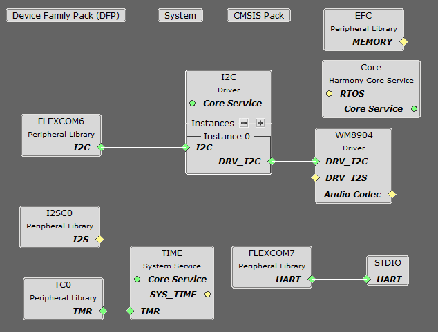
Note that in this basic example, the I2SC component of the SAM G55 does not use a Harmony 3 DMA driver, neither does it use SAM G55 Peripheral DMA Controller (PDC).
Harmony Core Block
Start MCC for the project in order to add the Harmony and the application code components. The Board Support Package (BSP) for the G55 Curiosity board should be selected first from the Available Components.
Next, the Harmony core is selected without FreeRTOS. Answer Yes to all questions except for the one regarding FreeRTOS; answer No to that one.
Audio Codec Component Blocks
G55Audio WM8904 Daughter Board Component Block
Under Audio\Templates, double-click on WM8904 Codec Template. Answer Yes to all questions. This loads the WM8904 Codec component along with associated I2C and I2S driver components.
Harmony Code Configuration Options
Each block in the MCC Project Graph may need to be configured through parameters for the specific application. These parameters are accessed by selecting the block with the mouse, and appear in the Configuration Options window, where they can be edited.
Audio Codec Configuration
The G55Audio WM8904 Codec Configuration
Using the G55Audio and the WM8904 Audio Codec Daughter Board:
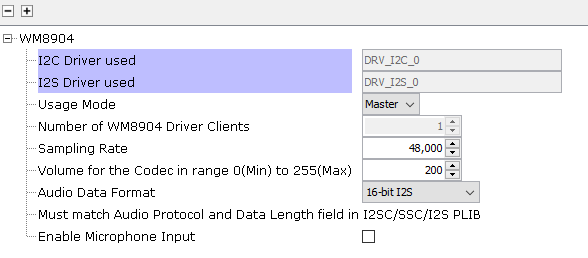
The WM8904 codec uses a I2C interface for configuration and control register setting and I2SC interface. The settings are unchanged from the generated values.
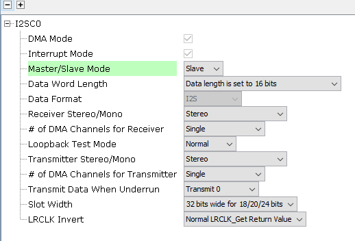
The I2SC0 peripheral driver is used to transfer 16 Bit Stereo data.
The I2C blocks can be used without changes to the configuration
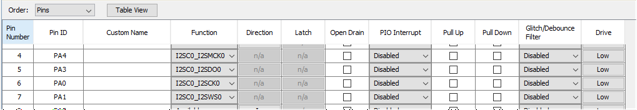
Pin Configurations
Clock Manager
The clock configuration diagram is shown using Tools/Clock Configuration menu.
The I2S clocks are setup for 48 kHz sampling rate, with stereo 16 bit samples, giving a 32 bit sample frame.
G55 Audio Clock Generation
The clock configuration diagram is shown using Tools/Clock Configuration menu selection.
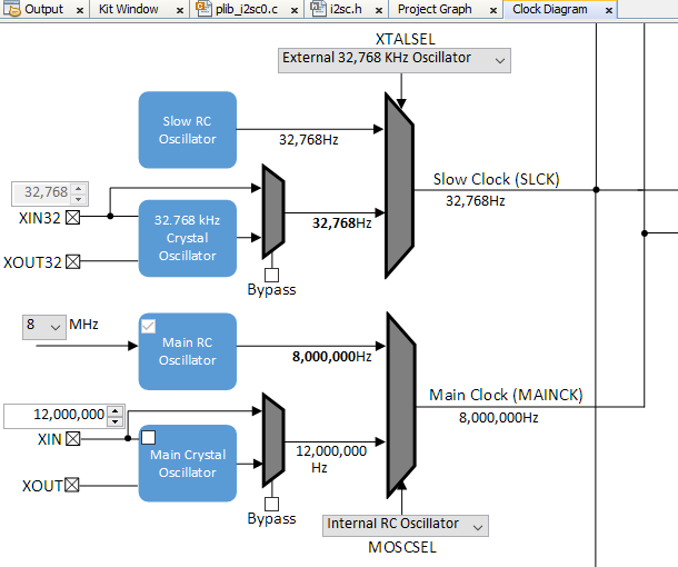
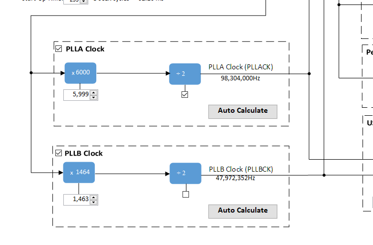
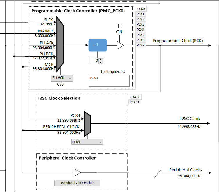
PLLA is used for the peripheral clocks, including I2SC.
Harmony Code Generation
All the needed drivers, middleware, libraries and application framework code can be generated from the MCC blocks (MCC components) placed in the MCC Project Graph,
The generated framework code is placed under the firmware/src/config directory under the name of the configuration used for the Harmony 3 project. The initial application code is located in the firmware/src directory app.c and app.h files, which utilize the framework drivers, middleware and library APIs located in definitions.h located in the config directory.
All Harmony applications first execute the SYS_Initialize function, located in initialization.c. This is executed from the main function to initialize various subsystems such as the clock, ports, BSP (board support package), codec, timers, and interrupts. The application APP_Initialize function in app.c is executed last in the generated SYS_Initialize routine after the system initializations have completed.
The SYS_Tasks function (located in tasks.c) is used to update the WM8904 driver, timers etc., as well as the application state machine (APP_tasks routine in app.c). This function is executed from the main polling loop. The polling loop executes SYS_Tasks repeatably in an infinite loop to perform the updates.
The application utilizes a simple state machine (APP_Tasks executed from SYS_Tasks) with the following functions
- Opens the WM8904 codec for configuration.
- Repeatedly writes the Sine Tone Wave values over I2SC0.
Building the Application
This section identifies the MPLAB X IDE project name and location and lists and describes the available configurations for the demonstration.
Description
The parent folder for these files is audio_apps/apps/simple_tone_generator/. To build this project, you must open the audio_apps/apps/simple_tone_generator/firmware/sam_g55_audio.X project file in MPLAB X IDE.
MPLAB X IDE Project Configurations
This table lists and describes the supported configurations of the demonstration, which are located within ./firmware/src/config.
| Project Name | BSP Used | Description |
|---|---|---|
| sam_g55_audio.X | sam_g55_audio_wm8904 | This demonstration runs on the SAM G55 Curiosity Audio board with the Wm8904 Codec. |
Configuring the Hardware
This section describes how to configure the supported hardware.
Using the SAM G55 Curiosity Audio and the WM8904 Daughter Board:
The G55Audio board and the WM8904 Audio Codec Daughter Board only requires the daughterboard to be connected to the X32 Header as shown below. The I2S Jumpers should all be set as shown, with jumpers placed toward the blue Line-In jack, not the pink Microphone-In jack.
Jumper J305 on the G55Audio board shall select PA18.
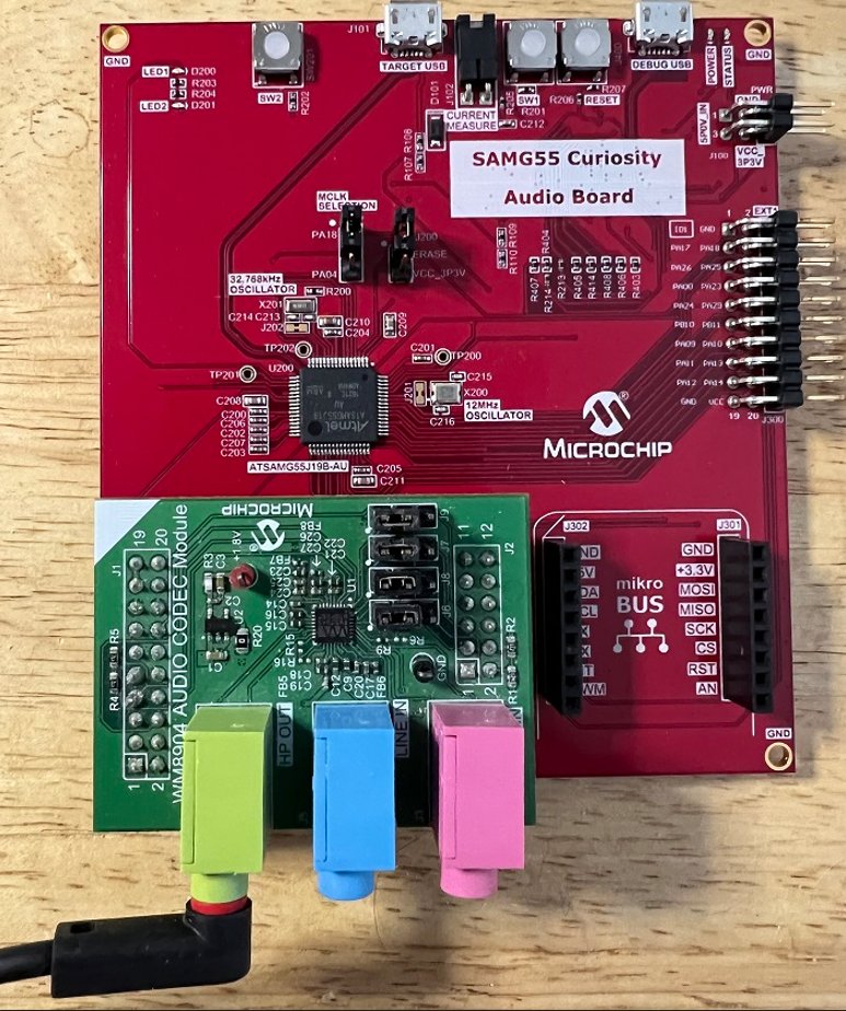
Connect headphones to the green HP_OUT jack of the Codec Daughter Board (as shown in the above figure).
As shown, the G55 Audio Curiosity will be programmed through the USB cable connected to the EDBG micro-mini connector. Program debug can also be performed over USB this connection.
Running the Demonstration
This section demonstrates how to run the demonstration.
Description
Compile and program the target device. While compiling, select the appropriate MPLAB X IDE project. Refer to Building the Application for details.
Do the following to run the demonstration:
- Configure the hardware, as described in the previous section, for the selected MPLAB-X project.
- Connect power to the board, compile the application and program the target device. Run the device.
Control Description
None