
4.1 Use Case 1 Output Filter Computation
In Use Case 1: Stereo Class D Amplifier with External Differential Power Stage, the positive terminal drives the positive alternates of the output signal (with the negative terminal shorted to ground), and the negative terminal drives the negative alternates (with the positive terminal shorted to ground). As a result, the output signal in this use case is predominantly made up of sharp spikes on either the P or the N side, rather than a modulated 50% PWM as in Single-Ended mode.
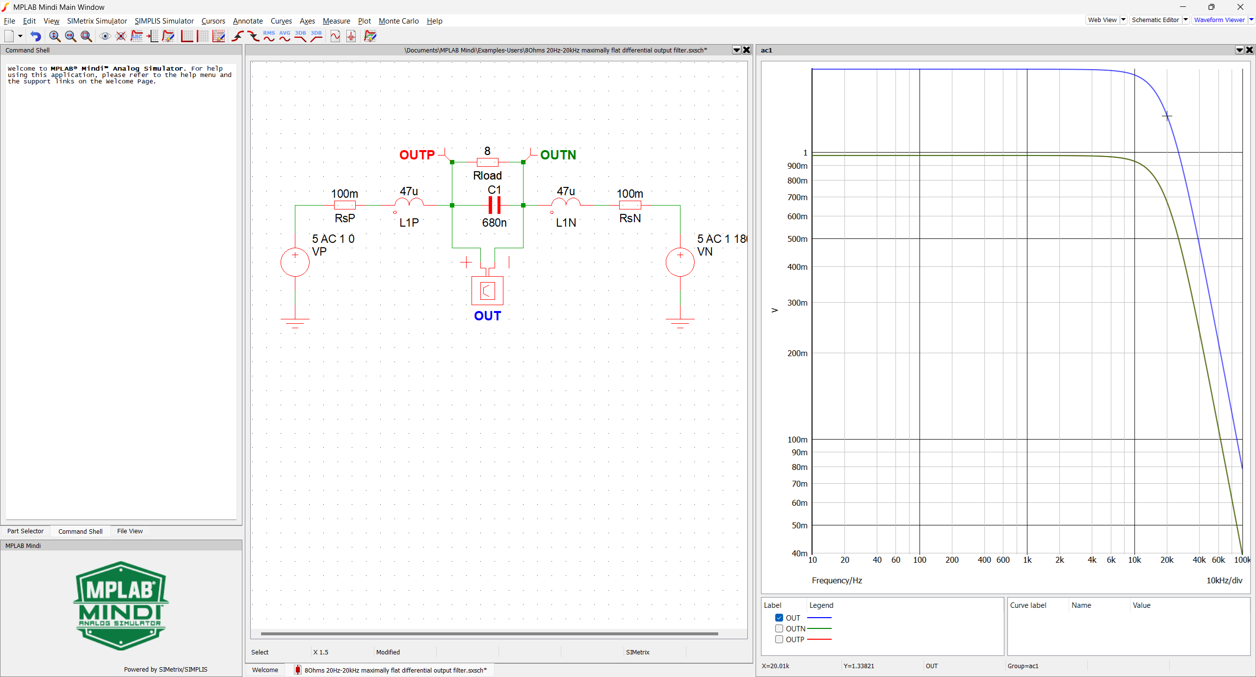
There is no major difference from the Single-Ended mode case regarding the component value computation (see Use Case 2 Output Filter Computation). However, the inductance is split into two devices, each having half of the overall value to preserve the circuit’s symmetry. Thus, the load should not be subjected to significant DC voltage, so the high-value serial capacitor can be omitted.
This can be simulated with Mindi™ using the 8Ohms 20Hz-20kHz maximally flat differential output filter.wxsch file, available from the MPLAB® Mindi Analog Simulator Software Library (see the Appendix).
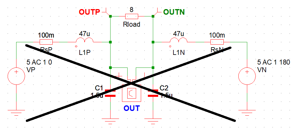
No smoothing filter operation in Differential mode:
- Do not omit the specific smoothing filter when driving a capacitive load.
- Do not add a capacitor in parallel with the load without implementing additional serial inductors.