
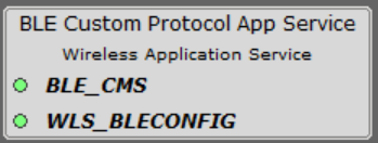
4.1 Bluetooth® Low Energy Custom Protocol Application Service Component
Custom Protocol Service will provide the custom protocol option for the all 10 characteristics in each customized service through write/write with response, based on the selection in Customized Service component. Given the potentially vast variations in user-defined protocols, our configuration GUI will be designed to be both highly flexible accommodating these variations and intuitive, allowing users to configure protocols with ease. The current design plan focuses solely on the server role.
For packet reception, the custom system service component is responsible for decoding packets according to the customer-defined protocol. It offers a dedicated callback function for each operation code, allowing the customer to implement actions specific to that operation. The custom protocol service generates all the necessary glue logic, ensuring seamless invocation of these callback function.
For packet send response and notify ,The Custom System Service component provides helper APIs to frame and send packets.
| Dependency Component | Dependency Type | Description |
|---|---|---|
| Customized Service | Mandatory | Enable protocol option over Customized service |
| BLE Config Service | Mandatory | Generate necessary BLE code configuration |
Component Configuration
Based on the number of services and characteristics selected in Custom Service component, the Custom Protocol service will display option to enable custom protocol enabled option for the selected characteristics. The BLE Custom Protocol Service allows users to define a custom protocol by assigning specific roles to each byte in the header and footer through the GUI . The available role options for each byte depend on the selection made in the previous byte. For example, if the user selects “Sequence number”, that option would not be available for consecutive bytes. If MSB is selected by user in any field then, the next field will be auto-selected as LSB.
| Byte Number | Role Options |
|---|---|
| Byte 0 |
|
| Byte 1 |
|
| Byte 2 |
|
| Byte 3 |
|
| Byte 4 |
|
| Byte 5 |
|
| Byte 6 |
|
| Byte 7 |
|
If the user is selecting a start delimiter for the header, they need to provide delimiter values to ensure clarity. Similarly, for the operation code, the user must specify the number of commands, the name of each command, and the command's ID.
| Byte Number | Role Options |
|---|---|
| Byte 0 |
|
| Byte 1 |
|
| Byte 2 |
|
| Byte 3 |
|
| Byte 4 |
|
| Byte 5 |
|
Similar to the start delimiter, if the user is selecting the end delimiter for the footer, they need to provide the end delimiter value to ensure clarity. If the CRC is selected, the user needs to provide the corresponding CRC polynomial value. For CRC/Checksum, the user also needs to specify the offset from which the calculation must start.
- Enable App Code
Generation: Users can generate a demonstration code by enabling the
Enable App Code Generation option, as illustrated in the following
figure. Follow the steps mentioned in the demonstration code generation for app
code generation.
Figure 4-2. Enable App Code Generation 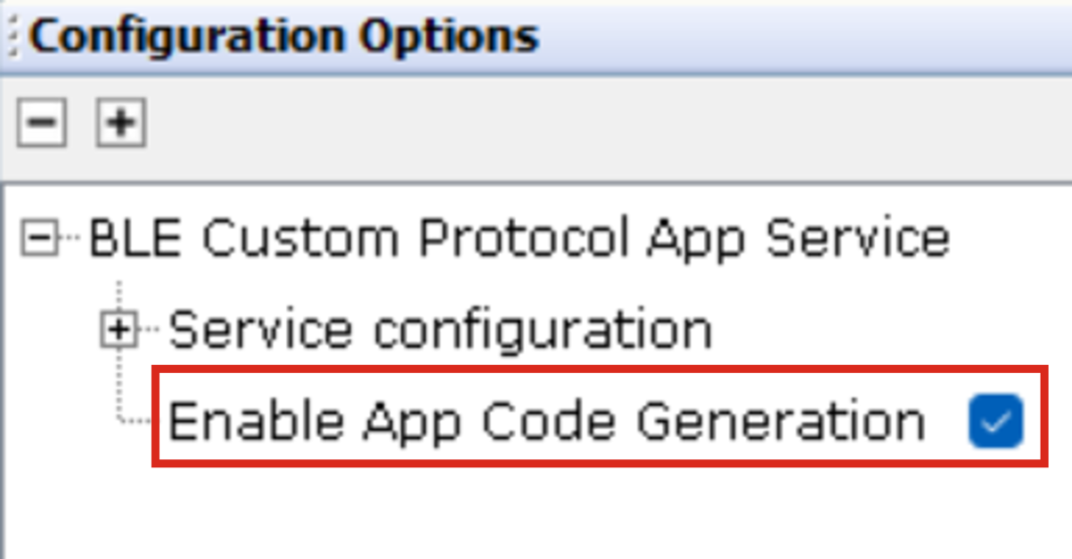
- Custom Protocol: Users can
enable custom protocols for characteristics within specific services, based on
the number of services and characteristics selected in the customized service
component.
Figure 4-3. Custom Protocol 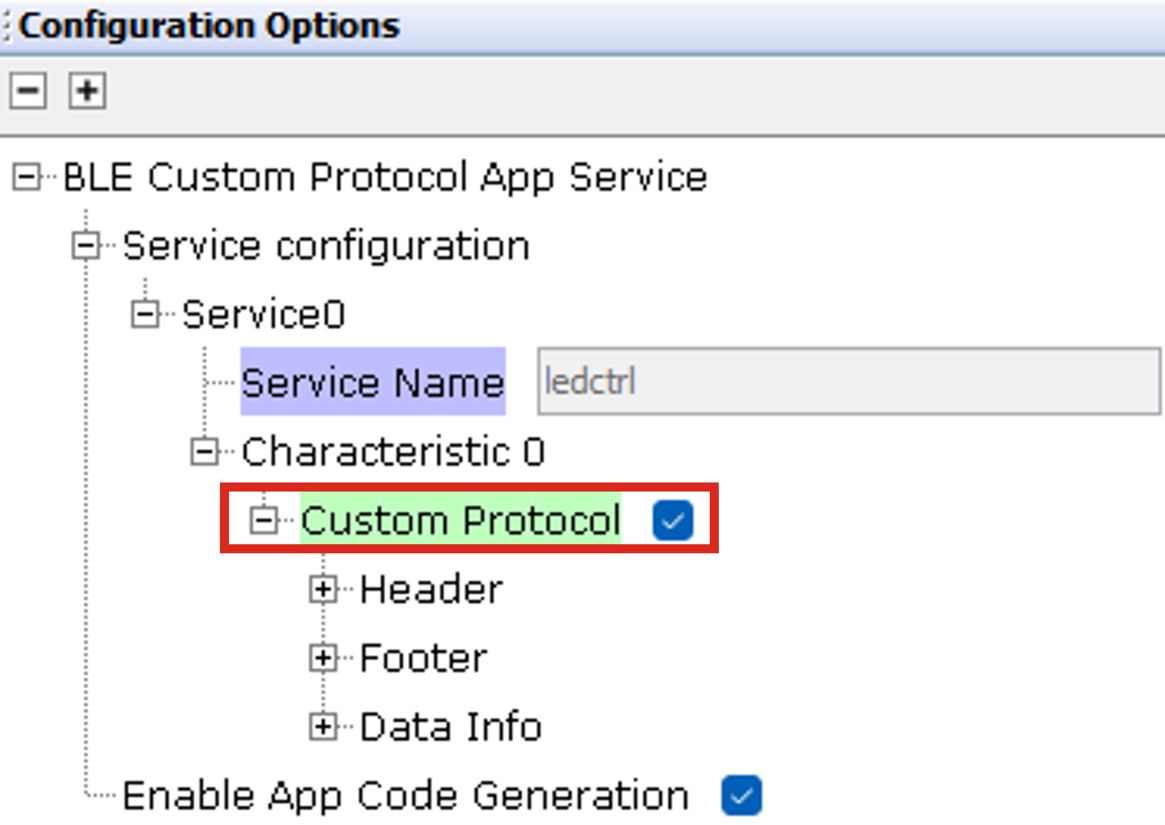
- Byte Role Selection: For
byte role selection, the default option will be “UNUSED”. If the user chooses a
different role option other than any MSB role or “UNUSED”, the next byte will be
activated with the default option “UNUSED”. If the user selects an MSB role in
any field, the subsequent byte or bytes will be automatically selected.
Figure 4-4. Byte Role Selection 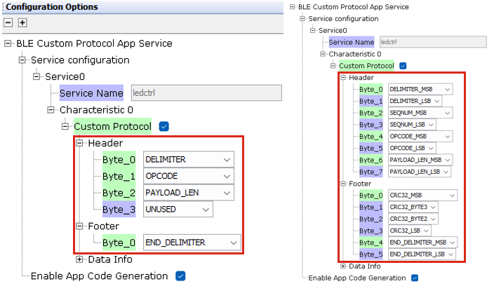
- Data Info Options: Based
on the CRC and delimiter selection in the bytes, the data information will
provide options for selecting the CRC8/16/32 polynomial (in binary), the
CRC/Checksum start byte (to specify the byte from which CRC/Checksum calculation
muat begin), delimiter, and end delimiter. Additionally, the data information
will include an option to enable escape characters if required. Escape character
is used to indicate that the following character must be treated differently, to
avoid confusion with delimiters.
Figure 4-5. Data info Options 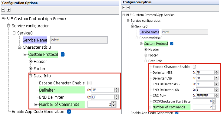
- Command Information: Users
can input command information as part of the data information if the opcode is
selected for a byte role. For each command, users must provide a command name
and opcode, with a maximum of 50 commands allowed.
Figure 4-6. Command Information 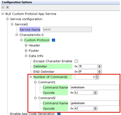
Sequence Number Check
The default sequence number check follows the algorithm described below:
- The code first compares the received sequence number with the expected sequence number. If they are equal, it means the received sequence number is valid.
- If the received sequence number is valid, the code updates the expected sequence number to the next expected value by incrementing it by 1. It also ensures that the sequence number wraps around to 0 after reaching the maximum value.
- If a BLE disconnection occurs, the expected sequence number value will be reset to 0.
CRC Calculation
The user must provide the CRC polynomial and the starting offset from which the CRC
calculation must begin. The CRC will be calculated on the data starting from the
"starting offset" up to, but not including the "CRC offset". Default CRC8, CRC16, or
CRC32 functions using a standard CRC algorithm with a predefined initial value of
0xFF, 0xFFFF, or 0xFFFFFFFF,
and a user-defined polynomial value.
Polynomial
To provide the CRC polynomial, let us take the polynomial (x^8 + x^2 + x + 1) as an example.
- Identify the highest degree term, which is (x^8). This corresponds to the 9th bit (since we start counting from 0).
- Identify the other terms: (x^2), (x^1), and (x^0) (which is the constant term 1).
Now, write down the binary representation:
- (x^8) corresponds to the 9th bit (from the left), which is 1.
- (x^7) is not present, so the 8th bit is 0.
- (x^6) is not present, so the 7th bit is 0.
- (x^5) is not present, so the 6th bit is 0.
- (x^4) is not present, so the 5th bit is 0.
- (x^3) is not present, so the 4th bit is 0.
- (x^2) is present, so the 3rd bit is 1.
- (x^1) is present, so the 2nd bit is 1.
- (x^0) is present, so the 1st bit is 1.
Putting it all together, the binary representation of the polynomial (x^8 + x^2 + x + 1) is: 100000111. However, to represent it as an 8-bit number, you need to drop the 9th bit, resulting in the value 00000111 for CRC8 calculation. This binary representation must be provided as input in the polynomial field.
Similarly, users can find the binary representation for their CRC16/32 polynomials by following the same steps.
Checksum Calculation
If a user opts for checksum calculation, they must provide the starting offset from which the calculation must begin. The checksum calculation will consider the data from the starting offset up to, but not including, the checksum offset. The default checksum8/16/32 function will return a checksum value by summing all the considered packet bytes.