4.3 Bluetooth® Low Energy Custom Protocol Application
This section assists users in generating a demo application using the BLE custom protocol application service component and also helps them verify the generated demo application. This example demonstrates the implementation of a BLE custom protocol server application.
Users have the option to either run the precompiled application example
.hex file on the WBZ451 or WBZ351 Curiosity Board to experience the demo, or to
follow the steps required to develop this application from the beginning.
These examples are designed to build upon each other incrementally. It is recommended to follow the examples in sequence, starting with the basic concepts and gradually advancing to more complex topics.
Recommended Reading
- BLE Software Specification
- Getting Started with WME Bluetooth Low Energy Applications
- Bluetooth® Low Energy Custom Protocol Application Service Component
- Project Generation with Bluetooth® Low Energy Custom Protocol App Service Component
Hardware Required
| Tool | Qty |
|---|---|
| WBZ451 or WBZ351 Curiosity Board | 1 |
| Micro USB cable | 1 |
| Android/iOS Smartphone | 1 |
Software Requirement
-
MPLAB X IPE: For programming the precompiled hex file.
- MPLAB X IDE: For programming the application example.
- Teraterm: Terminal Emulator for displaying UART output.
Programming the Precompiled Hex File or Application Example
Programming the .hex File using MPLAB X IPE
- Precompiled
.hexfile is located in “<Harmony Content Path>\apps\ble_cps_app\hex” folder. - For more information on the
programming steps, refer to the Programming a Device in MPLAB IPE section.Note: Users must choose the correct device and tool information.
Programming the Application using MPLAB X IDE
- Follow the steps mentioned in Running a Precompiled Example
- Open and program the
application example “
ble_cps_app_xxxx.X” where xxxx refer to device (for example: WBZ451, project file:ble_cps_app_wbz451.X) located in “<Harmony Content Path>\wireless_apps_ble\apps\ble_cps_app\firmware” using MPLAB X IDE
For more details on finding the Harmony content path, refer to Installing the MCC Plugin.
Demonstration
This application illustrates the implementation of a BLE custom protocol on the Curiosity board. The on-board RGB LEDs and UART serve as the user interface during the demonstration.
UART Settings
- Baud Rate/Speed: 921600 bps
- Parity: None
- Data Bits: 8
- Stop Bits: 1
- Flow Control: None
- Character Encoding: UTF-8
LED Behavior: The user can turn ON/OFF the Red, Green, and Blue LEDs in the RGB LED of the WBZ451 Curiosity Development Board through a packet that has a start delimiter, opcode, length, and end delimiter using BLE GATT client app
Testing
- Connect the WBZ451/WBZ351
Curiosity Board to the PC and program it with the precompiled
.hexfile or the specified application example. - Open TeraTerm and configure as mentioned below:
Terminal Settings
- Baud Rate/Speed: 921600 bps
- Parity: None
- Data Bits: 8
- Stop Bits: 1
- Flow Control: None
- Reset the board. After reset, the device will be advertising device name
“
ble_cps_app". - Launch the Microchip Bluetooth
Data (MBD) application on the mobile device.
- Open the BLE Connect sub-application and initiate a scan for devices by selecting START SCAN.
- Look for the device labeled as “
ble_cps_app” in the scan results. - Establish a connection with the device, refer to the following figure for guidance on the demonstration.
Figure 4-16. Scan and Connect 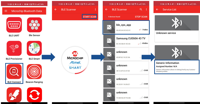
- Once the BLE connection is
established, select Generic Information from the service list and
navigate through the app as illustrated in the following figure to compose and
send a hex packet to the device.
Figure 4-17. Select Characteristic 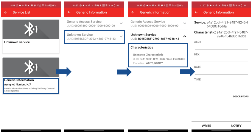
- To enable notifications, click on
the notification icon. Users can send a hex packet by entering the hex value in
the hex tab, as illustrated in the figure below. There are two commands
available:
- One to turn the Red, Green, and Blue LEDs in the RGB LED ON/OFF
- Another to retrieve the LED status.
0x01to turn ON and0x00to turn OFF. When retrieving the LED status, no specific payload is required, so the payload length can be set to zero.- To set the LED state and
turn the Red, Green, and Blue LEDs ON/OFF, use the hex packet (For
example,
7EA103010000EFto turn ON Red LED). There is no specific response for this command. - To retrieve the LED state
and check the status of the Red, Green, and Blue LEDs, use the hex
packet (For example, 7EA200EF). The response will be sent as a
notification for this command (For example,
010000indicates Red LED is ON), as illustrated in the following figure.
Note: On the WBZ351 Curiosity board, users can control only the GREEN LED by sending the command7EA103000100EF. Commands intended to control the RED or BLUE LEDs, such as7EA103010000EFfor the RED RGB LED, will not affect the RGB LED status on the WBZ351 Curiosity board. These commands will only change the state of the GPIO pins (PB0/PB5). Similarly, a status response of010000indicates the state of GPIO Pin PB0.Figure 4-18. Send Packet 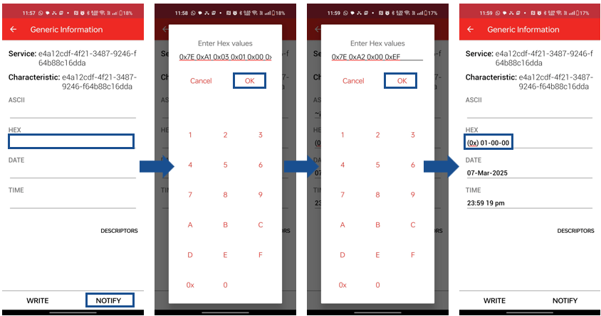
- The user can view the received
payload in the TeraTerm console, as illustrated in the following figure.
Figure 4-19. Console 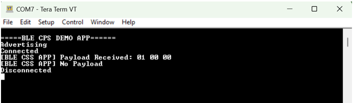
Developing the Application from Scratch using MCC
- Configure the customized
service and custom protocol app service as illustrated in the following
figure. For byte selection, choose OPCODE and set the number of
commands to 2.
Figure 4-20. Configure Customized Service 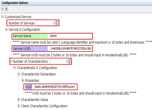
Figure 4-21. Configure Custom Protocol App Service 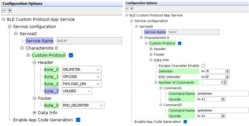
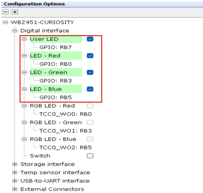
- Set up the LEDs in the System
Hardware Definition as illustrated in the image below. For instructions on
configuring the debug console, refer to the section Enabling Digital
Input/Output and Communication Interfaces Through System Hardware
Definition (SHD) component in Getting Started with WME Bluetooth
Low Energy Applications from Related Links.
Figure 4-22. Configure LEDs