3 Getting Started with WME Bluetooth® Low Energy Applications
Introduction
This chapter provides guidance on creating a new Bluetooth® Low Energy
application using the WME “BLE Config App Service” component, enabling digital IO and
communication interfaces, outlining the initial steps involved in developing a Bluetooth Low
Energy project with this app service component.
Note: In this tutorial "Curiosity Board"
refers to WBZ451/WBZ351 Curiosity Boards.
Adding BLE Config App Service Component
to Project Graph and Selecting the Device
After Creating a New MCC Harmony Project, if project graph is not visible, launch the
MPLAB Code Configurator from the toolbar.Figure 3-1. MCC
To add the BLE Config App Service
component to the project graph, go to Device Resources>Libraries > Harmony
> Wireless > Application Services.Figure 3-2. BLE Config App Service
All Bluetooth Low Energy related
components will be added into the project graph. accept dependencies or satisfiers by
selecting Yes.
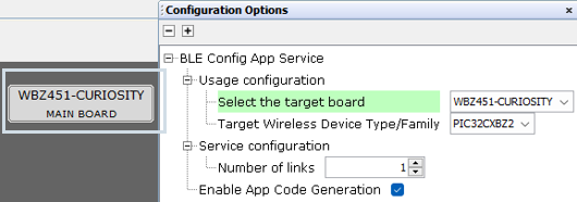
To select the target board, navigate to
the BLE Config App Service, then choose the Configuration Option. From the
Usage Configuration menu, select the appropriate board under the Select Target
Board option.
Note: Default board
selected would be “CUSTOM-BOARD”. For generating application source code, “Enable App
Code Generation” must be selected.
For WBZ451
Device
Figure 3-3. Project Graph
Figure 3-4. Board Selection and Enable App
Code
For WBZ351 Device
Figure 3-5. Project Graph
Figure 3-6. Board Selection and Enable App
Code
Configuring FreeRTOS
Default FreeRTOS settings remain unchanged.
Select FreeRTOS component from the project graph. Change the settings from Configuration
Options if required. Figure 3-7. Default Settings
Heap Size Configuration
For WBZ451 Device:
Configure the Total heap size to 40960Figure 3-8. Total Heap Size
For WBZ351 Device:
Configure the Total heap size to 73728
Figure 3-9. Total Heap Size
Note: By default, the “Total heap size” is
set to a value which might not be sufficient to a specific project. If the total heap size
is not enough, vApplicationMallocFailedHook( ) will be caught. User can
adjust the "Total heap size" to avoid this situation. If any application-specific FreeRTOS
settings need to be adjusted, they will be detailed in the application-specific
documentation.
Enabling Digital Input/Output and
Communication Interfaces Through System Hardware Definition (SHD)
This section outlines the process for enabling the digital Input/Output interface and
Communication Interfaces on the Curiosity Boards using the BLE Config App Service
component.
When the device is selected, the
System Hardware Definition component will be automatically added to the project
graph based on the chosen device. Example as shown below.Figure 3-10. WBZ351 SHD Component
Figure 3-11. WBZ451 SHD Component
Select the SHD component and open Configuration Options menu.
To enable USART interface, select
USART console interface under USB-to-UART interface section.
Note: User can configure the Digital Interface
by selecting the LEDs and switches according to the application requirements.
Figure 3-12. SHD Component
Configuration
Selecting the USART Console
Interface adds the SERCOM0 and CONSOLE components to the project graph
and establish a connection between them. Accept dependencies or satisfiers by selecting
Yes.Figure 3-13. Auto insertion of CONSOLE and
SERCOM0
Configure SERCOM0 settings as
illustrated below.Figure 3-14. SERCOM0 Settings for
Applications
Default CONSOLE Configurations are
as shown below. The user can modify the configuration as required by the application.Figure 3-15. Console Settings
Configure SYSTEM component option
as illustrated below.Figure 3-16. SYSTEM Component Settings
Adding DEBUG Component for Debug and
Error Messages
This section outlines the process of adding DEBUG component to the project graph to
facilitate debugging and error messaging. The Debug System Service helps in adding debug
capabilities to application code by printing various levels of debug messages through the
debug console port.
Right click on CONSOLE
multiconnect capability labelled as SYS_CONSOLE.Figure 3-17. DEBUG Selection
Select Consumers>DEBUG.
DEBUG will establish a connection with CONSOLE. Figure 3-18. DEBUG Selection
Figure 3-19. DEBUG Connection
In the DEBUG Component Configuration Options, the default setting for Debug
Level is SYS_ERROR_DEBUG. Ensure to change it to
SYS_ERROR_INFO. Figure 3-20. DEBUG Settings
WME BLE Applications
Following are the list of WME BLE applications and links.