The event system enables direct peripheral-to-peripheral communication
and signaling. The event system consists of generators, channels, and users. A change in the
peripheral’s state is referred to as an event.
An event that takes place in one
peripheral (say source) can be used to trigger another event in a different peripheral
(destination). The term generator refers to the event of the source peripheral and the
term user refers to the event of the destination peripheral. The generator and the
source are connected via an event channel. The channel section lets you configure
available channels for a particular event generator source. There are two types of event
channels; Synchronous and Asynchronous. Asynchronous event control enables the event
input to qualify the output directly. For more details on event channels, refer the
hardware manual. This document explains the event system with an example of a timer
event (event generator) triggering the ADC conversion (event user) through a synchronous
channel.
Concepts and Principles
A typical example is to have a
timer (overflow or compare match) event to start an ADC conversion. In this example,
the timer (TCA) is the source and ADC is the action. Both will be connected via an
event channel.
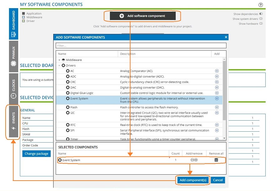
Create a new project using the ATtiny817.
Click on Add software component to add the event system driver.
A tab named EVENTS appears on the
left side of the screen.
Click on the EVENTS tab.
The GENERATORS and the USERS from the system drivers
will appear by default, such as Port and PORTMUX.
Overflow Timer Event Starts an ADC
Conversion
In this example, we have assumed
that only the event system driver was selected earlier.
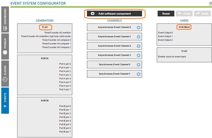
Click on Add software component to add the Timer driver.
The TCA0 is added as a generator and a user. The
overflow event is listed as a generator.
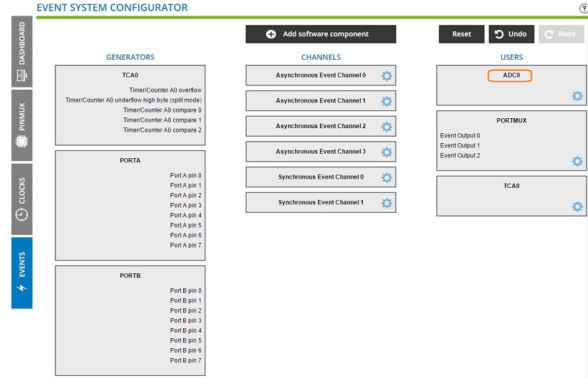
Click on Add software component to add the ADC driver.
The ADC is added as a user.
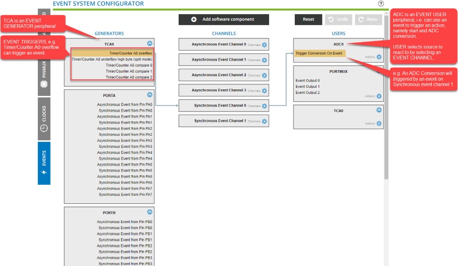
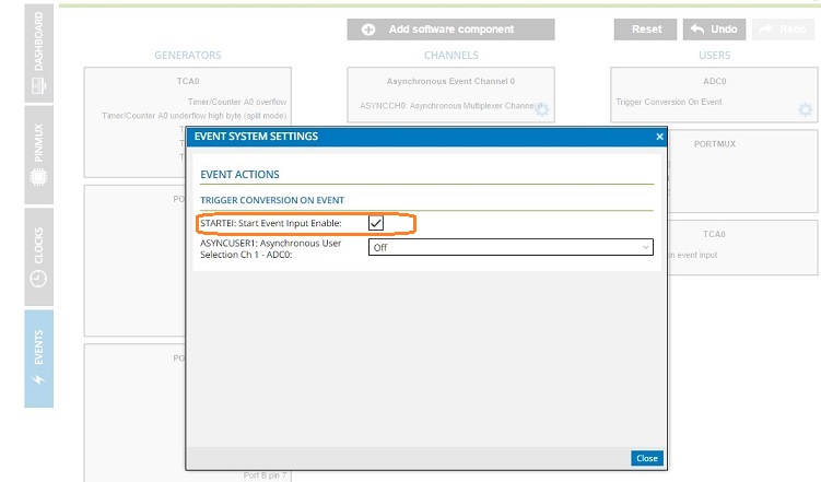
Start by dragging the TCA event generator (overflow) onto an Asynchronous
Event Channel 0, then try dragging this event channel onto the ADC. This
does not work because we have not yet enabled STARTEI (START Event Input
Enable) for the ADC. Click on the ADC0 configuration wheel, then check
"STARTEI" and close. You will now see that “Trigger Conversion on Event” is
present in the ADC0 as a specific event user. Now you can drag the event
channel onto this event (note: ADC0 should be grayed out when no specific
event users have been enabled).
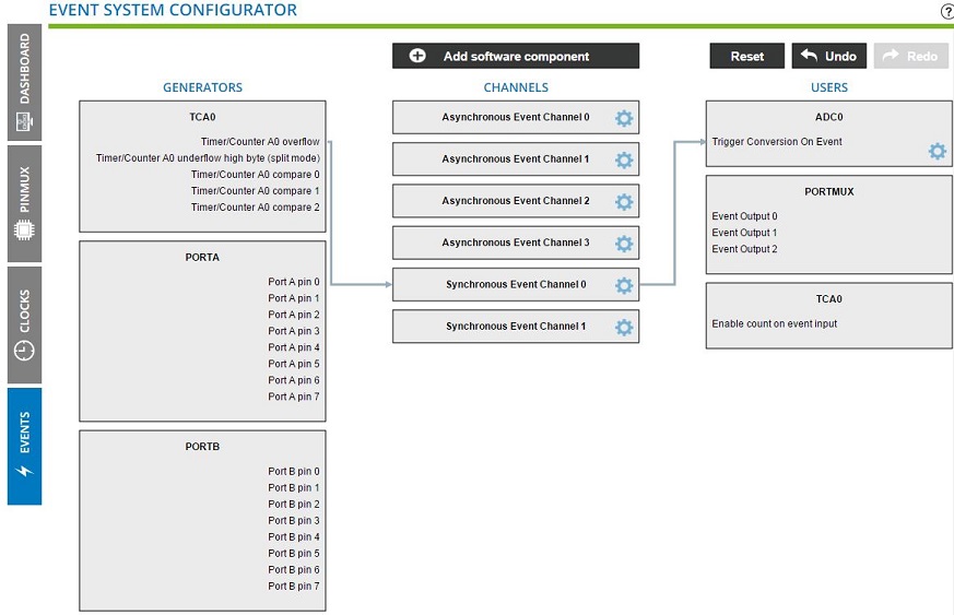
Next, connect the TCA event with the ADC: Click and drag the
Timer/Counter A0 overflow to the
Synchronous Event Channel 0 channel.
During drag and drop, only supported channels are
highlighted.
A connection is made between TCA and the event channel.
Click and drag the Synchronous Event Channel 0 to
the ADC0.
A connection is made between the event channel and the
Trigger Conversion On Event.
The online versions of the documents are provided as a courtesy. Verify all content and data in the device’s PDF documentation found on the device product page.