
4.4 PINMUX Configurator
The PINMUX Configurator presents an overview of all the configured pins.
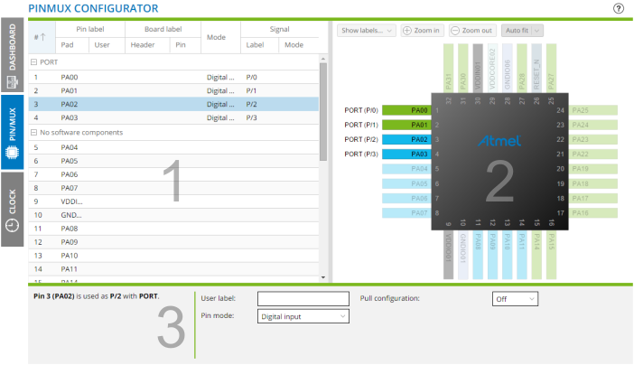
- Pin Assignment.
- Device Layout.
- Pin Details Editor.
From the Pin Assignment table you can:
- List pin number, pad, software component, mode, and signals
- Click on the column header to change the sort order
- Add columns by clicking on the header and select Columns
- Select a pin by clicking on the row, select more by holding the <SHIFT> or <CTRL> keys when clicking
From the Device Layout you can:
- Hover over a pin to highlight the corresponding pad in the Pin Assignment table
- Click on a pin to open the corresponding pad for editing in the Pin Assignment table
- Click in the center of the device to access web-based information for the device
The Pin Details Editor is used for setting properties for GPIO pins. Select one or more GPIO pins in the Pin Assignment table, and the Pin Details Editor will open at the bottom of the screen. Here you can assign a user label, select a pin mode, and configure the selected pin mode.
You can select multiple pins at once by pressing the <SHIFT+CTRL> keyboard keys while clicking on the list. This allows you to configure multiple pins at once.
If the pins selected are of different types, they may not support the same pin modes. You will only be able to configure settings that are common to the selected pins.