4.1 Setting Up the Hardware
(Ask a Question)This section describes how to connect all of the components required to run the demo.
To set up the hardware, follow these steps:
- Connect the test module device to a LAN using the Cat 6 cable.
- Connect the Host PC to the same LAN using the Cat 6 cable.
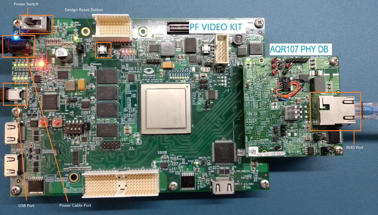
- Connect the host PC and the video kit through J12 of the video kit using the USB mini cable.
- Insert the Aquantia PHY daughter card on the FMC connector of video kit.
- Connect the Aquantia PHY daughter card and the test module using the Cat 6 cable. At the test module side use the 10Gbe variable data-rate port (for example, port 9).
- Connect the power supply cable to J20 of the video kit.
- Ensure that the following jumper settings are set on the video kit.
Table 4-1. Jumper and Switch Settings Jumper Default Position Functionality J15 Open SPI Target and Initiator mode selection. By default, SPI initiator. J17 Open 100K PD for TRSTn. By default, 1K PD is connected. J19 Pin 1 and 2 Default: XCVR_VREF is connected to GND. J28 Pin 1 and 2 Default: Programming through the FTDI. J24 Pin 2 and 4 Default: VDDAUX4 voltage is set to 3V3. J25 Pin 5 and 6 Default: Bank4 voltage is set to 1V8. J36 Pin 1 and 2 Default: Board power-up through the SW4. SW4 OFF (Pin 2–3 and 5–6 Positions) Power ON\OFF switch. SW6 OFF User slide switch. Default position: OFF. J20 12V Input 12V input to the board. - Power-up the Host PC and test module.
- Power-up the video kit using the SW4 slide switch.
The PolarFire USXGMII hardware is setup as shown in Figure 4-1. To program the PolarFire device, see the Programming the PolarFire Device section.