Running a Digital Signal Processing Application
After programming with the
Demo1_FIR_FILTER_Vx.x.dat file, follow these
steps:- On the FPGA Demo tab click the Input
Parameters tab.
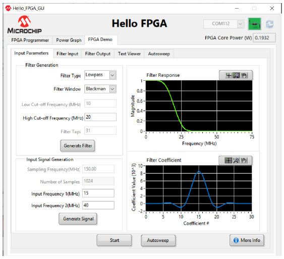
Figure . Running a Digital Signal Processing Application 
- Under the Filter
Generation group, configure the following information (see the
previous figure), and then click Generate Filter to
generate the filter coefficients:
- Filter Type
- Filter Window
- High Cut-off Frequency (MHz)
- Under the Input Signal
Generation group, enter the input frequencies, click
Generate Signal, and then click the Filter
Input tab to observe the result.
Figure . Filter Input Signal 
- On the Filter Input tab, click
Start to send the generated input signal and the
filter coefficients to the SmartFusion2 FPGA, and then click the
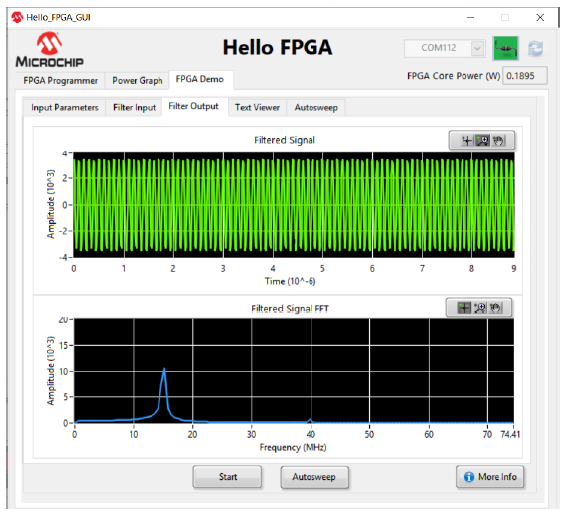
Filter Output to observe the result.
Figure . Filter Output Signal 
The filtered output from SmartFusion2 FPGA as per the filter configuration can be observed on the Filter Output tab.
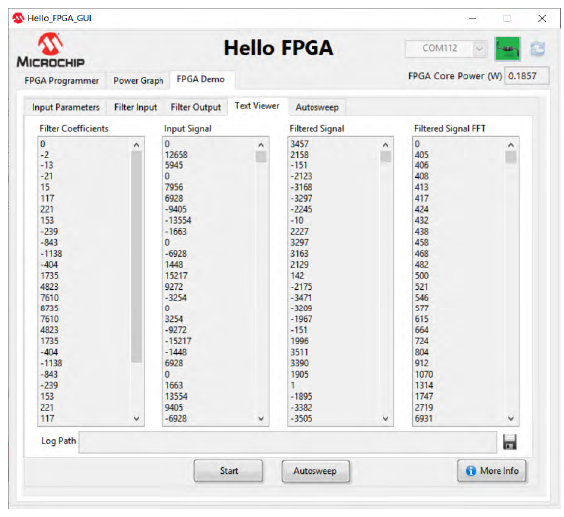
- To see the numerical values of the graphs plotted in the Filter
Input and Filter Output tabs, click the
Text Viewer tab.
Figure . Text Viewer 
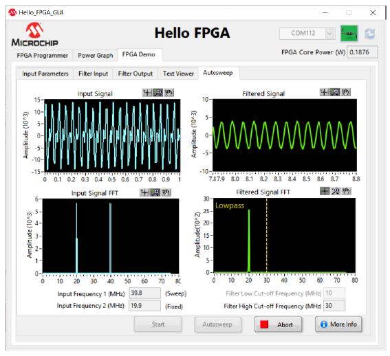
- Click the
Autosweep tab, the GUI automatically sweeps one of
the input signal frequencies (Sweep) through a range of values and sends to the
FPGA to perform filter operation. Filtered output from FPGA is displayed on the
right.
Figure . Sweep Signal Frequency 
