5.2 Creating an Application
With the bootloader code built and configured to the needed specifications, configure the target application to work alongside the bootloader instead of erasing the bootloader code from the device and programming the new target application over it. MPLAB X IDE allows the user to set various project configuration properties to match the bootloader configuration. The first step for completing this task is to create a blinking LED project.
-
Create a new MPLAB X IDE project.
Figure 5-41. New Application Project 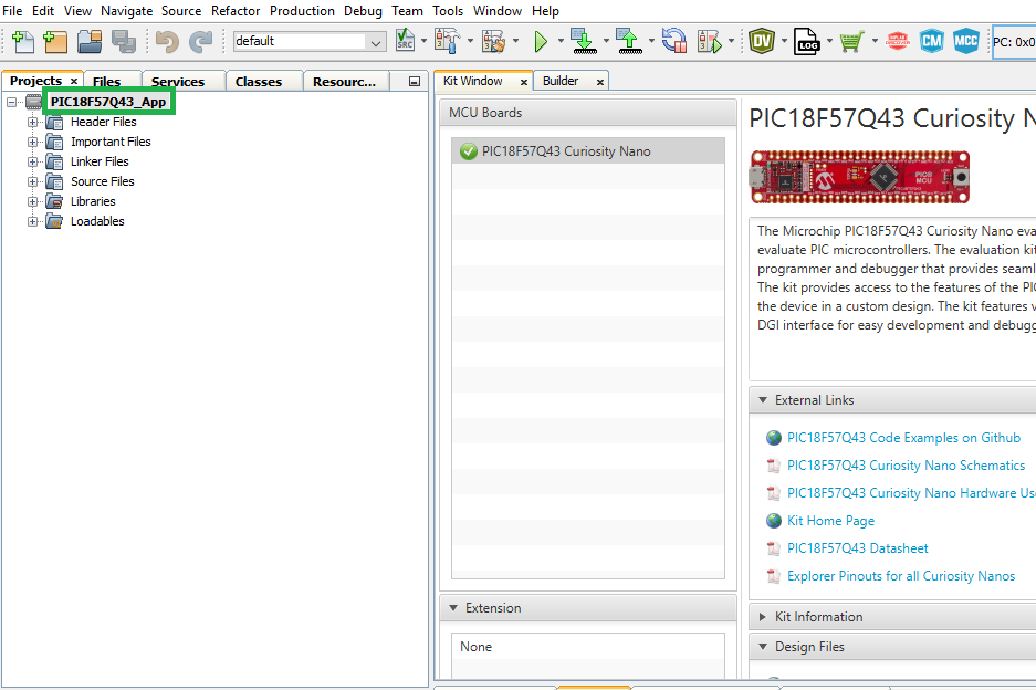
- MCC opens up automatically when a new
project is created. If not, click the MCC button in the menu bar to start the
MPLAB Code Configurator.
Figure 5-42. Open MCC 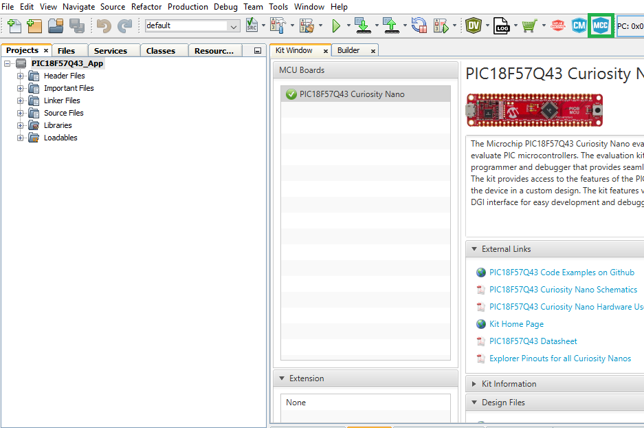
-
Configure the on-board LED by setting the RF3 pin. Set the Custom Name to LED.
Figure 5-43. LED Configuration 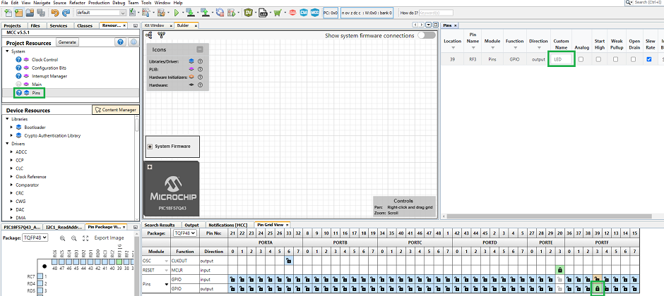
- Add the Delay driver from
Device Resources>Drivers>Timer to the project.
Figure 5-44. Delay Driver 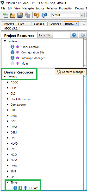
-
Press the Generate button in the Project Resources tab to generate the project code.
Note: Make sure to match the Clock Control and Configuration Bits settings to the bootloader project settings.Figure 5-45. Generate Application Code 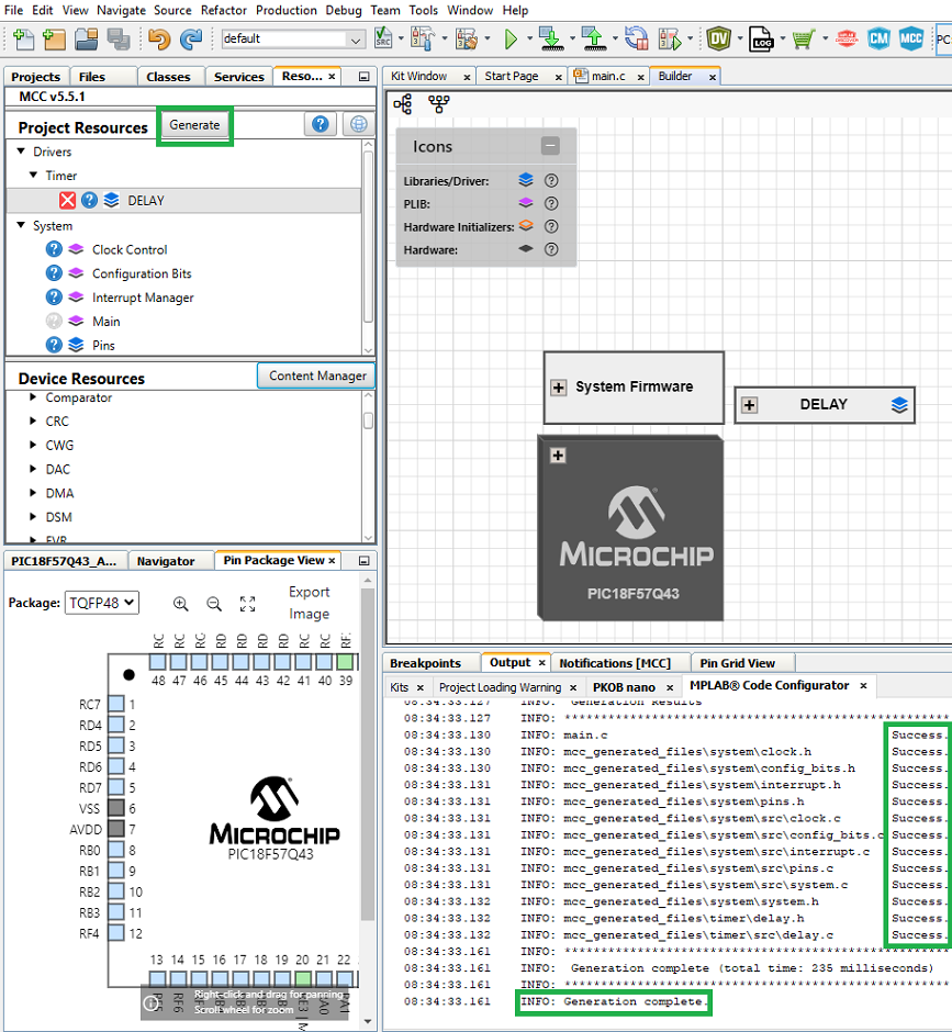
-
For a blinking LED application, add the following code to
main.cin Source Files under the project folder. Thedelay.hheader file must also be included in the main file.Figure 5-46. Blinking LED Code 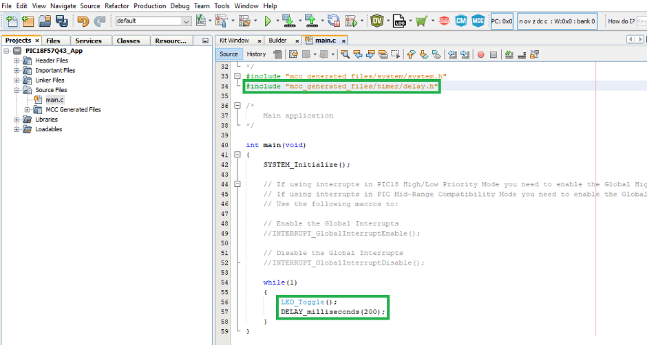
- Add the following code at the top of
the
main.cfile before the main function. This reserves the last bytes to hold the Checksum value. The address presented below in the__at()is PROGMEM_SIZE - 2, since the Checksum hash size used is two bytes. For PIC16 devices, this address is in words.Note: For Checksum, CRC16 and Check State Flag verification schemes, the hash size is two bytes. For CRC32, the hash size is four bytes.Checksum Verification Scheme
#include <stdint.h>
#ifdef __XC8__
#include <xc.h>
#endif
volatile const uint16_t
#ifdef __XC8__
__at(0x1FFFE)
#endif
applicationFooter __attribute__((used, section("application_footer"))) = 0xFFFF;
CRC32 Verification Scheme
#include <stdint.h>
#ifdef __XC8__
#include <xc.h>
#endif
volatile const uint32_t
#ifdef __XC8__
__at(0x1FFFC)
#endif
applicationFooter __attribute__((used, section("application_footer"))) = 0xFFFFFFFF;
CRC16 Verification Scheme
#include <stdint.h>
#ifdef __XC8__
#include <xc.h>
#endif
volatile const uint16_t
#ifdef __XC8__
__at(0x1FFFE)
#endif
applicationFooter __attribute__((used, section("application_footer"))) = 0xFFFF;
Check State Flag Verification Scheme
#include <stdint.h>
#ifdef __XC8__
#include <xc.h>
#endif
volatile const uint8_t
#ifdef __XC8__
__at(0x1FFFE)
#endif
applicationFooter __attribute__((used, section("application_footer"))) = 0x55;
Figure 5-47. Add Verification Settings in main.c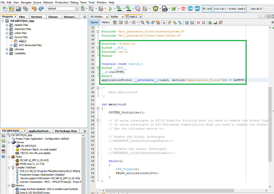
-
Configure the project properties. Go to File>Project Properties and select PIC18F57Q43 Curiosity Nano under Connected Hardware Tool, DFP version under Packs and the XC8 version under Compiler Toolchain.
Figure 5-48. Set Project Properties 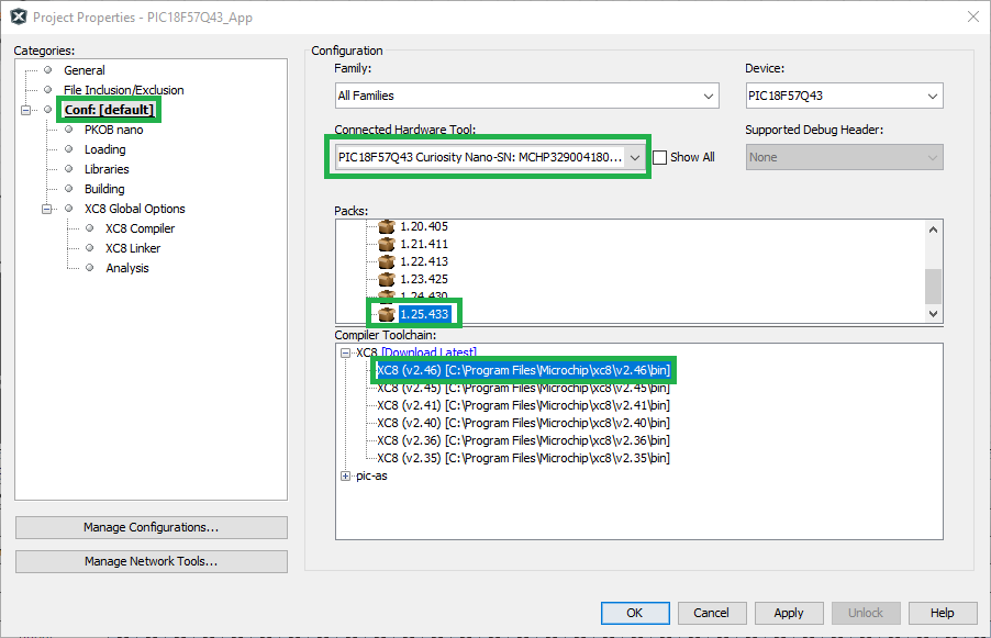
- Configure the linker setting for the
used verification scheme before proceeding to the next step in compiling the
project.Note: Check out the Compiler and Linker Settings section below for details on the configuration for PIC and AVR devices.
- Click Clean and Build to the generate the project hex file.
Compiler and Linker Settings
PIC
The following section is intended to provide an explanation of the compiler and linker settings utilized in the PIC18F57Q43 end application project. The example below uses the Checksum verification scheme for demonstration.
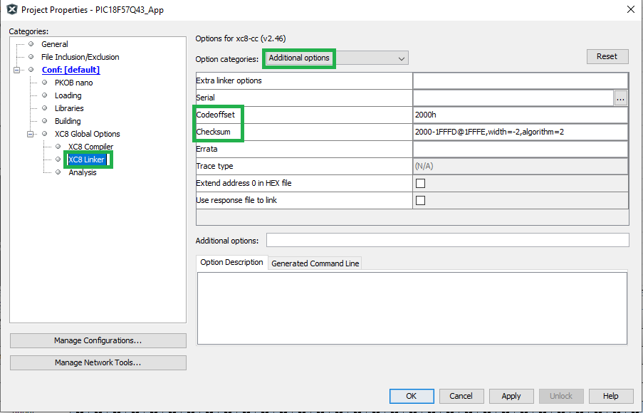
- Linker → Additional Options
- Codeoffset = 2000h
- Checksum = 2000-1FFFD@1FFFE,width=-2,algorithm=2
Here,
- 2000 → Bootloader offset value
-
1FFFD → Program Memory Size
-
Width → Width of Checksum – This value is used because the checksum calculated is two bytes and it will occupy the last two bytes of the Program Memory. For CRC32, the Cyclic Redundancy Check (CRC) value is four bytes and for CRC16, the CRC value is two bytes.
-
1FFFE → Checksum value will be stored here for two bytes
-
Algorithm → Checksum verification schemes algorithm value
Polynomial → Hexadecimal value used when calculating CRC. Refer to the Verification Schemes section for more information.
Linker Additional options setting for the verification schemes:-
CRC16 → 2000-1FFFD@1FFFE,width=-2,algorithm=5,offset=FFFF,polynomial=1021
-
CRC32 → 2000-1FFFB@1FFFC,width=-4,algorithm=-5,offset=FFFFFFFF,polynomial=04C11DB7
-
Checksum → 2000-1FFFD@1FFFE,width=-2,algorithm=2
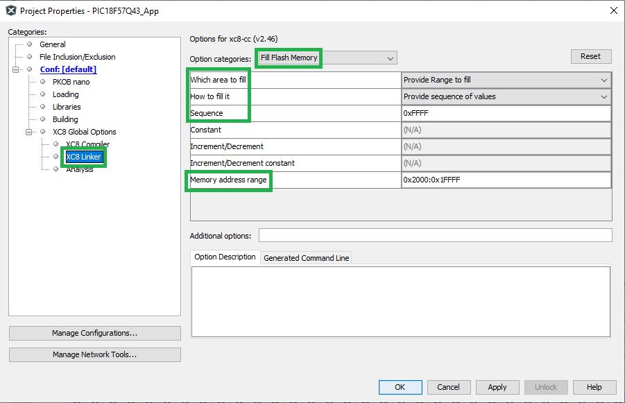
Open File>Project Properties. Add the below settings to the XC8 Linker>Fill Flash Memory. These steps enable the mentioned sequence to fill all the unused memory space in the generated hex file. Set the Memory address range to Application Start Address:End of Flash Memory.
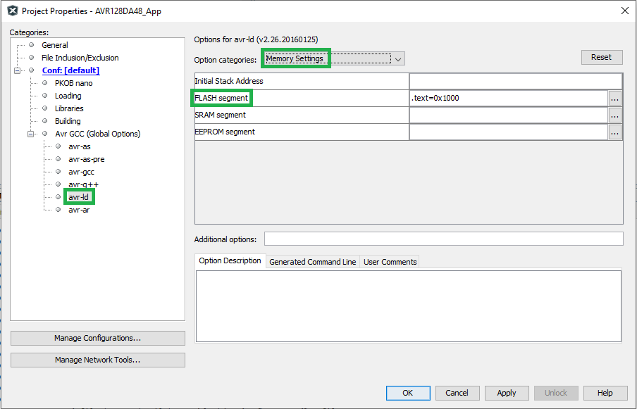
AVR
For AVR devices, a batch file execution is enabled in the Project Properties to fill the empty spaces in the application project with a given sequence. Follow the steps below to create the batch file.
- Right click the Source
Files>New>Other.
Figure 5-51. New Linker File 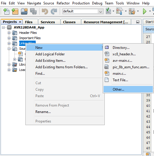
- In the New File window, select
Other under Categories and Empty File under File Types. Click Next.
Figure 5-52. New File Window 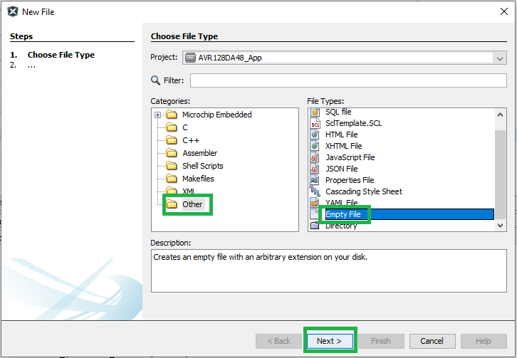
- In the File Name text box, enter
postBuild.batas the file name and click Finish.Figure 5-53. New postBuild.batFile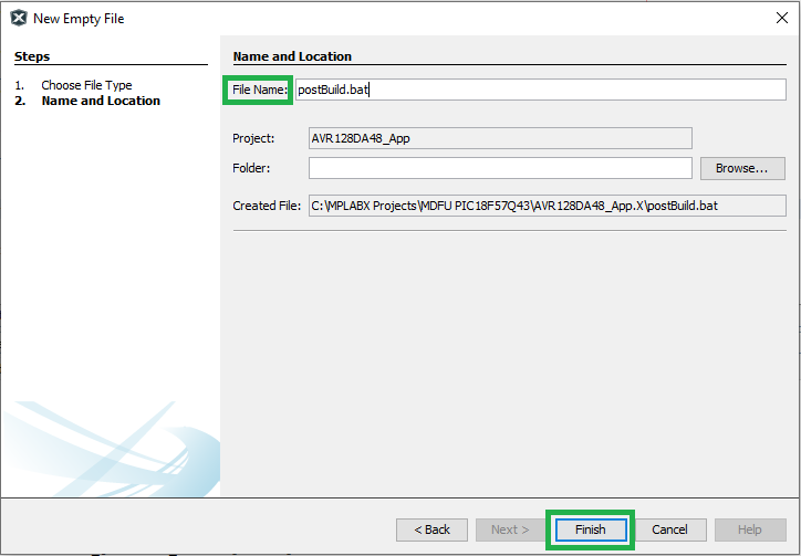
- Add the following lines to the
postBuild.batfile to configure the application section based on the verification scheme selected.- For all verification
schemes, to fill the unused space:
hexmate r0-FFFFFFFF,%1 -O%1 -FILL=w1:0xFF@0x2000:0x1FFFFHere,
0x2000 → Application Start Address
0x1FFFF → Program Flash Memory Range End Address
Checksum Verification- To perform the
calculation and store the result:
hexmate %1 -O%1 +-CK=2000-1FFFD@1FFFEg2w-2Here,
The application code can use memory addresses 0x2000-0x1FFFD. The 2-byte checksum value is placed at address 0x1FFFE.
CRC16 Verification- To perform the
calculation and store the
results:
hexmate %1 -O%1 +-CK=2000-1FFFD@1FFFE+FFFFg5w-2p1021
CRC32 Verification-
To perform the calculation and store the results:
hexmate %1 -O%1 +-CK=2000-1FFFB@1FFFC+FFFFFFFFg-5w-4p04C11DB7
Figure 5-54. postBuild.batFile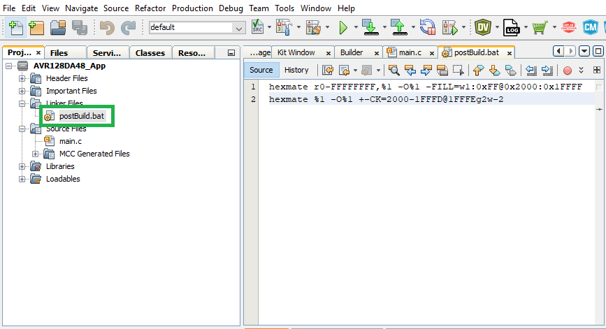
- For all verification
schemes, to fill the unused space:
- With the postBuild script
created, open Project Properties>Building. Enable the “Execute
this line after build” checkbox. Add the following lines in the text box below it.
postBuild${ShExtension} ${ImagePath}Figure 5-55. postBuild.batFile Execution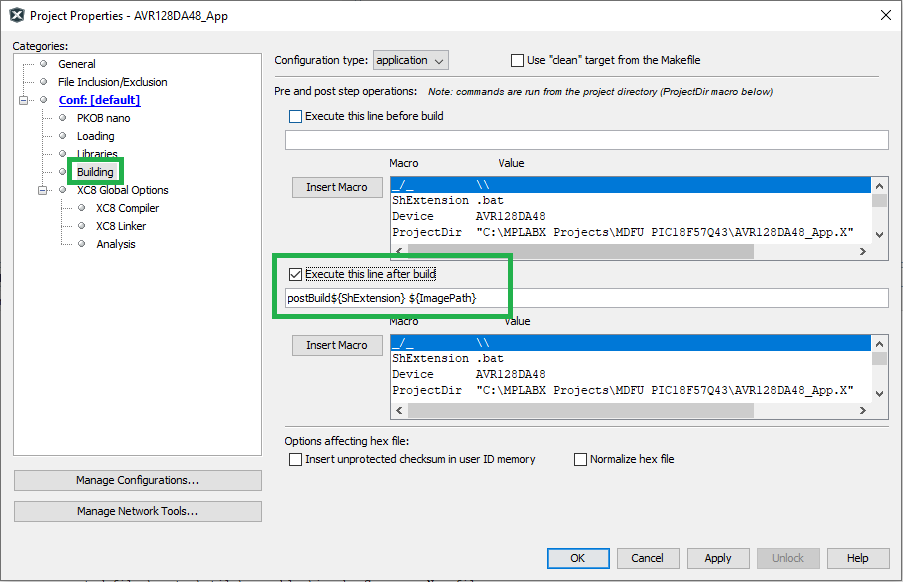
AVR - XC8 Compiler
-Ttext=<Application Start Address> -Wl,-u,applicationFooter
In XC8 Compiler-Preprocessing and messages, make sure to enable “Use CCI Syntax”.

AVR - GCC Compiler
With the bootloader client and the application projects created, the image file
can be generated by using the Firmware Image Builder ( pyfwimagebuilder) tool by combining the
bootloader_configuration.toml file and the application hex
file.
pyfwimagebuilder build -i PIC18F57Q43_App.X.production.hex -c bootloader_configuration.toml -o output.img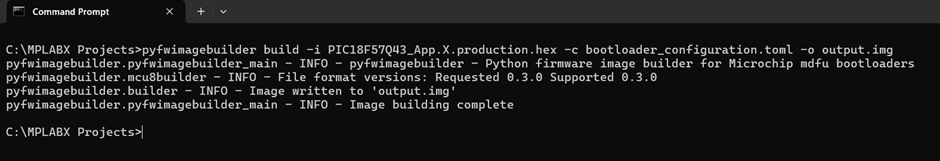
End Application Programming
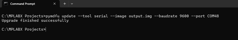
The newly-generated application image can be transferred to the target device using the Microchip Device Firmware Update (pymdfu) tool.
pymdfu update --tool serial --image output.img --baudrate 9600 --port COM48