5.1.3 Multi-Voltage I/O
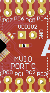
The AVR128DB48 Curiosity Nano MCU has support for Multi-Voltage I/O (MVIO). AVR128DB48 MVIO pins are connected to the edge connector at PC0-PC7. MVIO pins are capable of regular I/O-pin behavior.
MVIO can be configured in one of two supply modes:
- Single-Supply mode: All I/O pins, including MVIO-capable pins, are powered by VCC_TARGET. By default, VCC_TARGET is connected to VDDIO2 through a 0-ohm resistor (R204).
- Dual-Supply mode: MVIO-capable pins are powered by an external power supply connected to VDDIO2. Non-MVIO pins are powered by VCC_TARGET.
Dual-Supply mode allows MVIO-pins to be powered at different voltages than pins powered from VCC_TARGET.
Warning: The absolute maximum
external voltage range for the AVR128DB48 is 1.8–5.5V. Applying a higher voltage may cause permanent
damage to the board.
By default AVR128DB48 Curiosity Nano board is configured for single-supply mode. To use Dual-Supply mode some hardware modifications are required.
Warning: Before any hardware
modifications are done, make sure the board is disconnected from USB or external
power.
- Disconnect resistor R204 connecting VDDIO2 to VCC_TARGET
- Connect a new power supply to VDDIO2 and ground at J212
- J212 does not have reverse polarity protection. Make sure to match polarity between the power supply and J212. Positive-polarity to J212-pin 1 and negative-polarity to J212-pin 2
The resistor R204, VDDIO2 and J212 can be seen in Figure 5-4.
 |
Warning: Applying an external
voltage to VDDIO2 pin without removing resistor R204 may cause permanent damage to the
board.
Warning: J212 does not have
reverse polarity protection. Applying voltage to the wrong pin may cause permanent
damage to the board.
