5.1 MCC Melody Example Components
Let’s explore what an example component is, as well as the difference between example and implementation.
5.1.1 Configuration, Code and Board
- Configuration settings of the component (building block) and potentially other components.
- Code snippets to add to your application (matching configuration settings).
- Board schematics, e.g., In Pin Grid View: Select an LED pin as an output, renaming it to LED.
Example Components are the next generation of assistance technology, further enhancing the user experience for the presented applications by seamlessly integrating with MCC. This integration allows users the convenient side-by-side placement of the configuration instructions and the components they are configuring. Moreover, users have the capability to generate code directly, streamlining the process by allowing for immediate copying and pasting within their MPLAB X IDE project.
5.1.2 Ecosystem Context for Example Components
The MCC Melody Example Components fit into the MPLAB ecosystem, specifically in the context of MPLAB Discover, as follows:
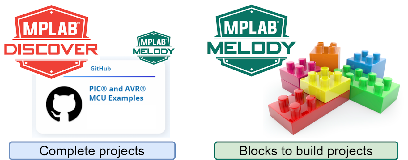
| MCC Melody Projects on MPLAB Discover / GitHub (Finished/Complete Projects) | MCC Melody Example Components (Project Building Blocks) |
|---|---|
| Quickly run a project with interesting functionality/technologies | Learn how to build a project using MCC Melody |
| May find full application examples | Individual Example Components have relatively simple examples, using 1 or 2 supporting components. However, they are designed so that functionality can be added with other Example Components. |
| Board specific | Range of boards - paired with schematic |
5.1.3 MCC Melody Example Components - The Basics
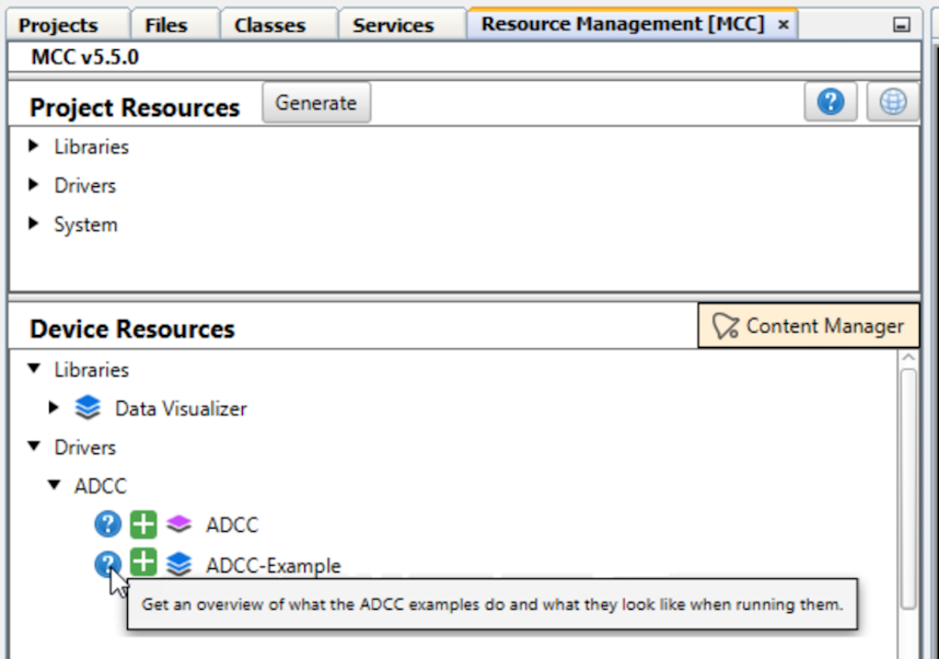
The following is an overview of what the Analog-to-Digital Converter with Computation (ADCC) examples do and what they look like when running them.
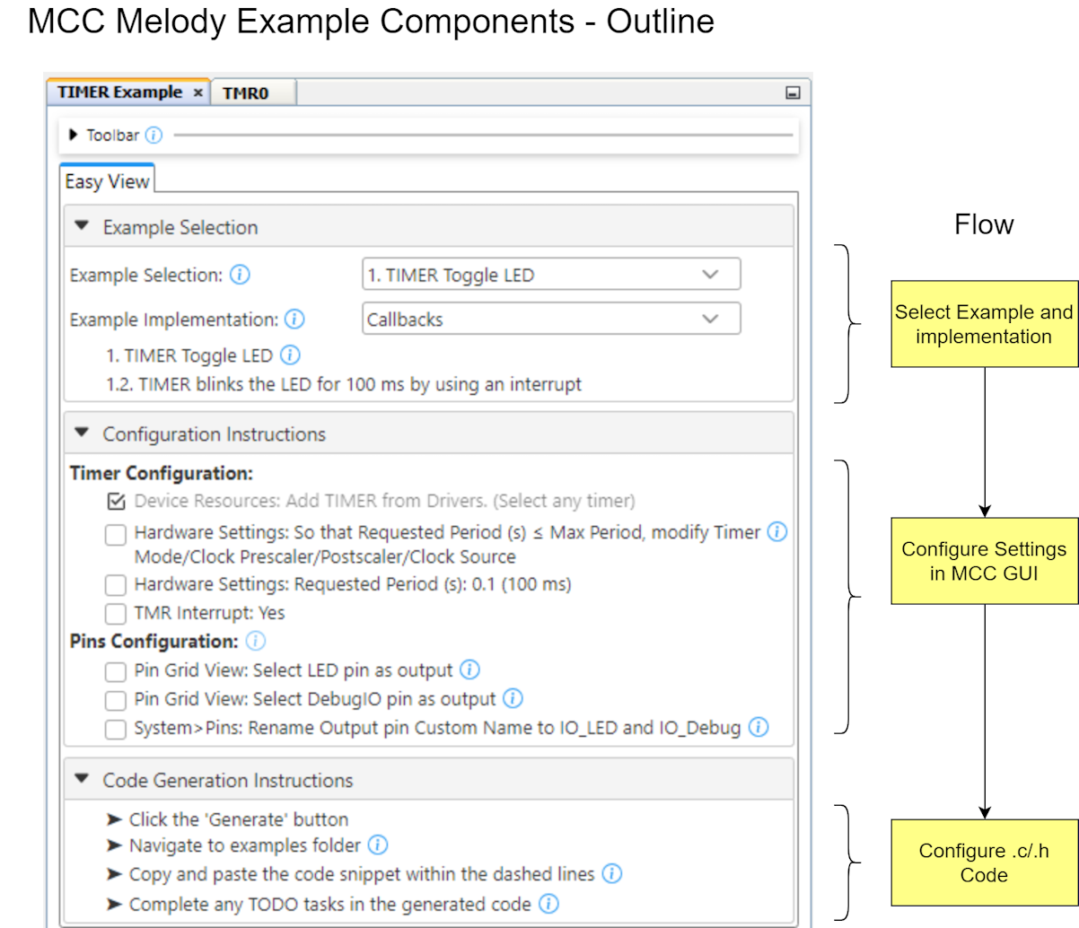
The basics of using an MCC Melody Example Components are as follows:
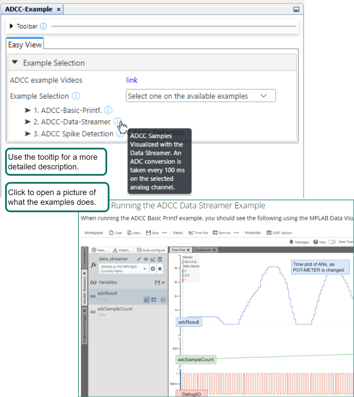
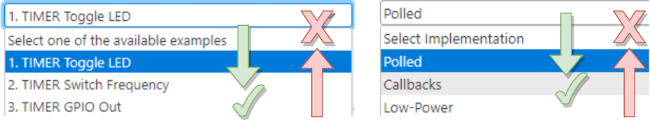
1. Select an example component
Before adding an example (component) to your project, click to open a link describing what the examples do.
- Tooltip - The example name is short, a more complete description can be found in the adjacent tooltip
- Link - An annotated picture of running the example, e.g. with the Data Visualizer
3. Selecting an implementation
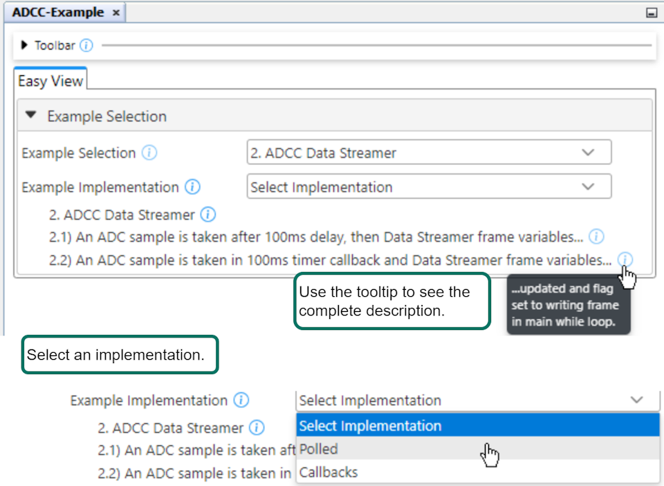
- Polled implementations - Generally the simplest, to quickly understand the code
- Callback implementations - More flexible, to build on to an existing application
5.1.4 Supported Workflows
- 1→2→3 , or start directly on any particular example, e.g., 3
- Polled→Callbacks→Low Power
(or State Machine), or directly to a particular implementationCAUTION:
Not supported!
3→2→1, or Low Power (or State Machine) →Callbacks→Polled
5.1.5 MCC Melody UART Driver: CNano Schematics and UART
When using a Curiosity Nano, how do you easily find the Serial/CDC UART?
When plugging in a Curiosity Nano evaluation kit, MPLAB X IDE will open the Kit Window tab, which contains a number of useful links for the particular board that you have.
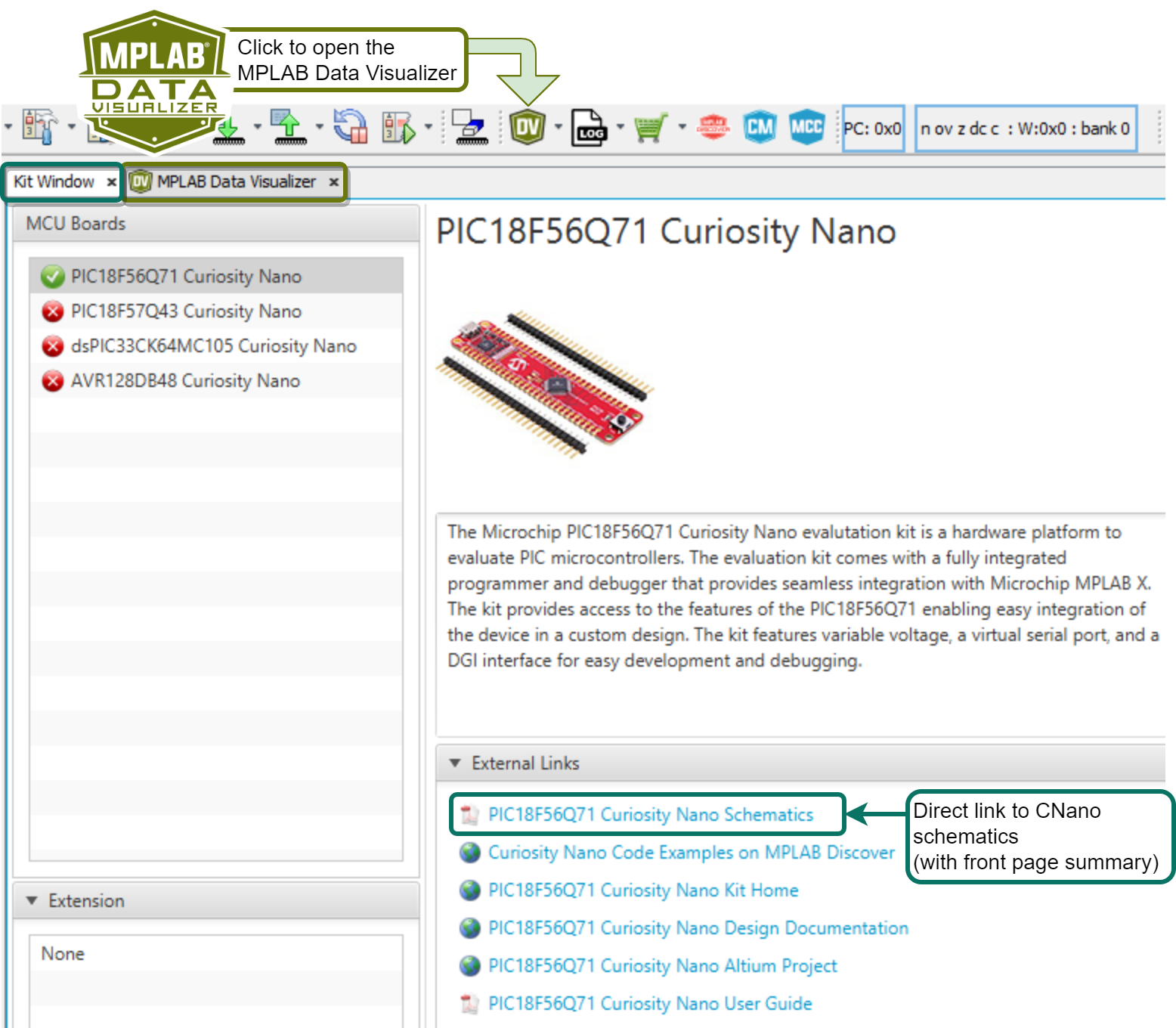
Click the Curiosity Nano Schematics link, as shown in the image above, to quickly find the UART connected to the USB CDC of the CNano debugger. In addition, you can very quickly find the LED and BUTTON and the DebugIO pin(s).
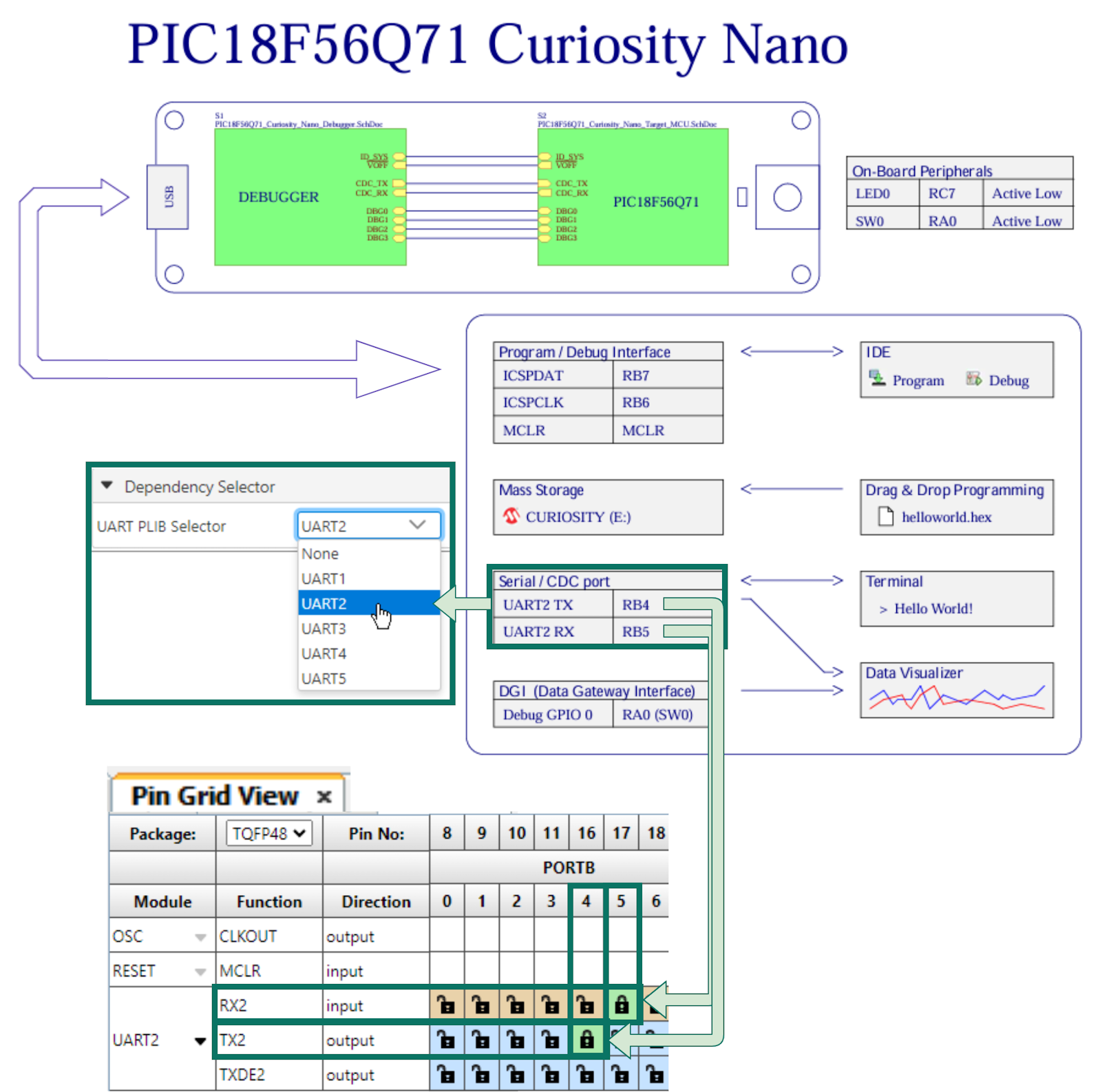
- The image above depicts an example for the Q71, where UART2 is connected to the Serial/CDC port, UART Tx is RB4 and Rx is RB5.
-
Different UARTs can be used for certain PIC MCUs due to Peripheral Pin Select (PPS). In this case, the specific pins used for UART Tx and UART Rx play a significant role.
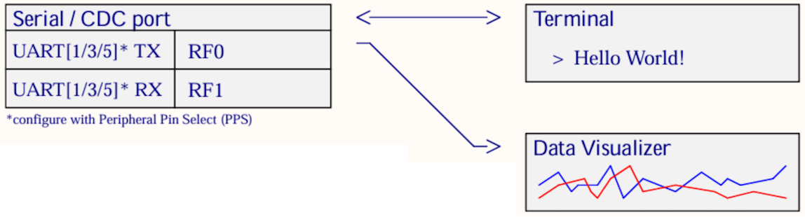
- It is possible to connect from the Serial/CDC port on the Curiosity Nano to either the Data Visualizer or a separate terminal program.
- For an introduction to the Data Visualizer, see Visual Debugging with MPLAB® Data Visualizer.
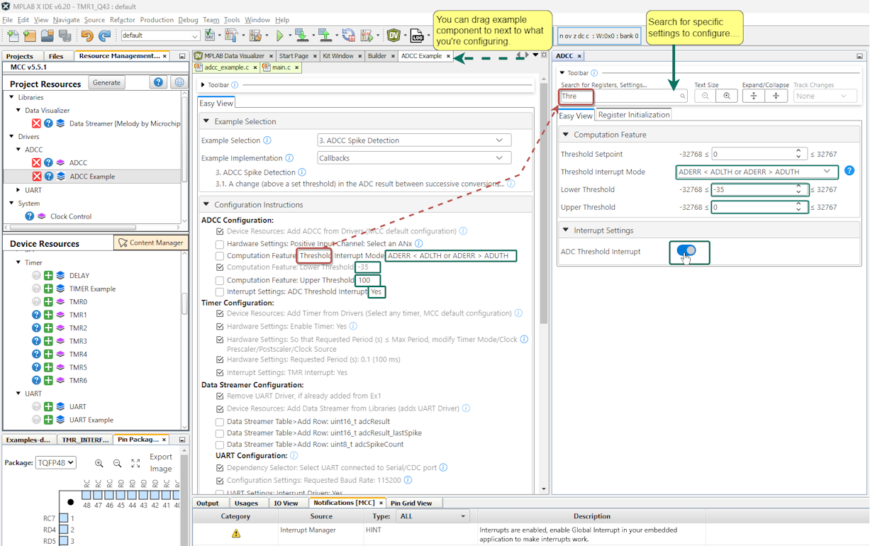
5.1.6 MCC Melody Example Components - Copy/Paste Code
Once you completed the configuration instructions from an MCC Melody Example Component, the next step is to generate code.
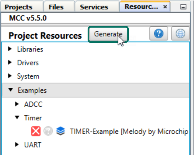
- From the Projects tab,
navigate to MCC Generated
Files>examples>Component-Example>
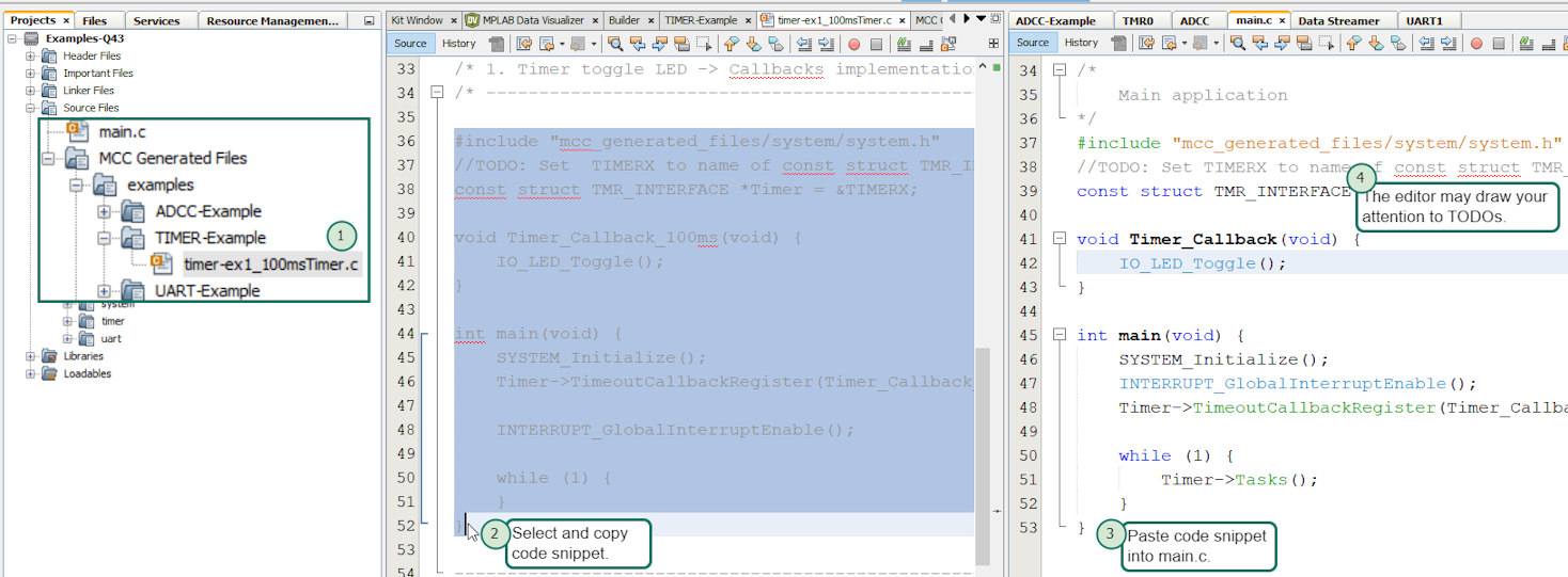
example_name.c. - Copy the code snippet within the dashed lines.
- Paste the code snippet into your
application code.
- Replacing the empty
main.c, if you are starting a new project. - Paste sections of code more selectively, if you are building on an existing project.
- Replacing the empty
- Pay attention to any TODOs in the comments or any items that are underlined in red by the MPLAB X IDE editor.
5.1.7 MCC Melody GPIO Configuration
This section details common tasks related to GPIO configuration, such as selecting LED, DebugIO, UART Tx/Rx pins, renaming pins, etc.
5.1.7.1 MCC Melody GPIO: Configuring LED and BUTTON pins
Many examples include General Purpose Input/Output (GPIO). Since the default naming convention for PINs in MCC Melody starts with IO_, all the I/O pins in examples follows this convention. For example, IO_LED or IO_BUTTON.
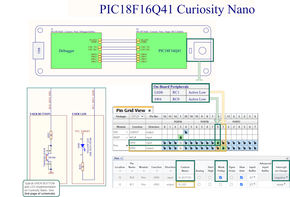
- Set the active low LED as output, rename to IO_LED.
- Set the active low BUTTON with no pull-up resistor as input, enable Weak Pullup, set Interrupt-on-Change to Negative.
5.1.7.2 MCC Melody GPIO: Configuring Debug GPIO
What are Debug GPIO pins and what can they be used for?
Debug GPIO pins are also provided on the Curiosity Nano via the Data Gateway Interface (DGI). Debug GPIO are particularly useful for a rough verification of application timing.
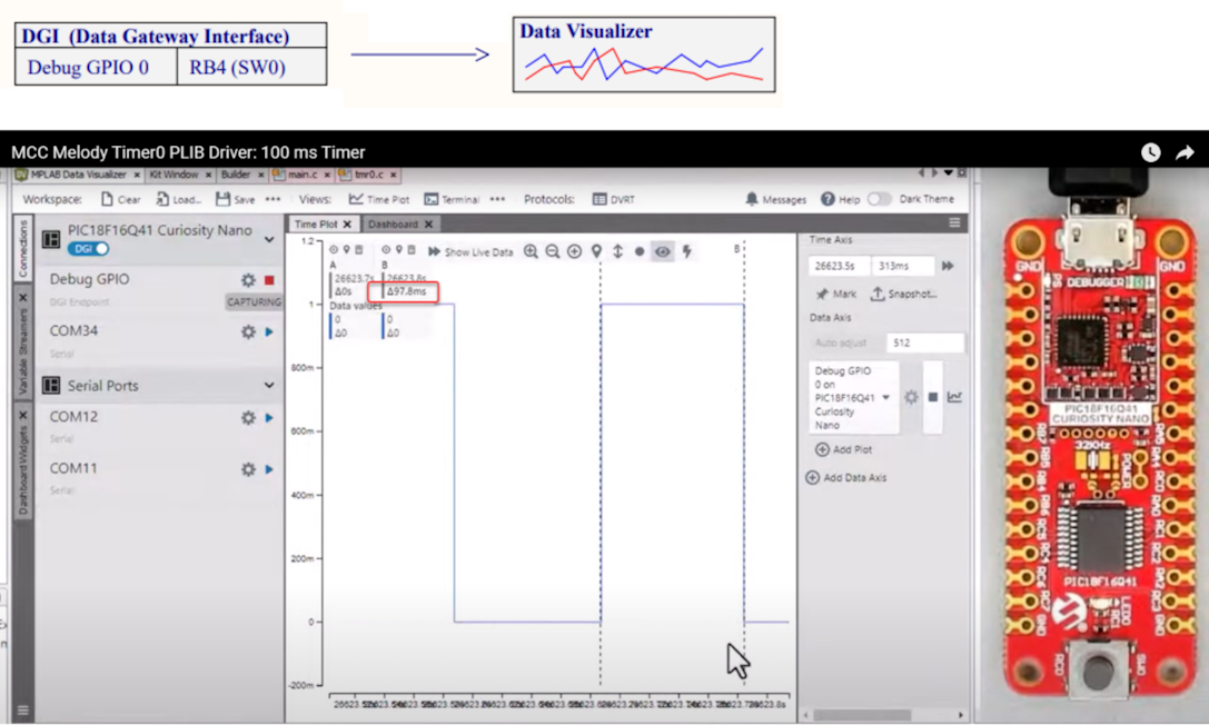
- Go to AVR TCA PLIB Driver, PIC Timer0 PLIB Driver for a video on how to use the MCC Melody 100 ms Timer.
- If you are new to MPLAB Data Visualizer, see Debug GPIO Hello World (Microchip University).
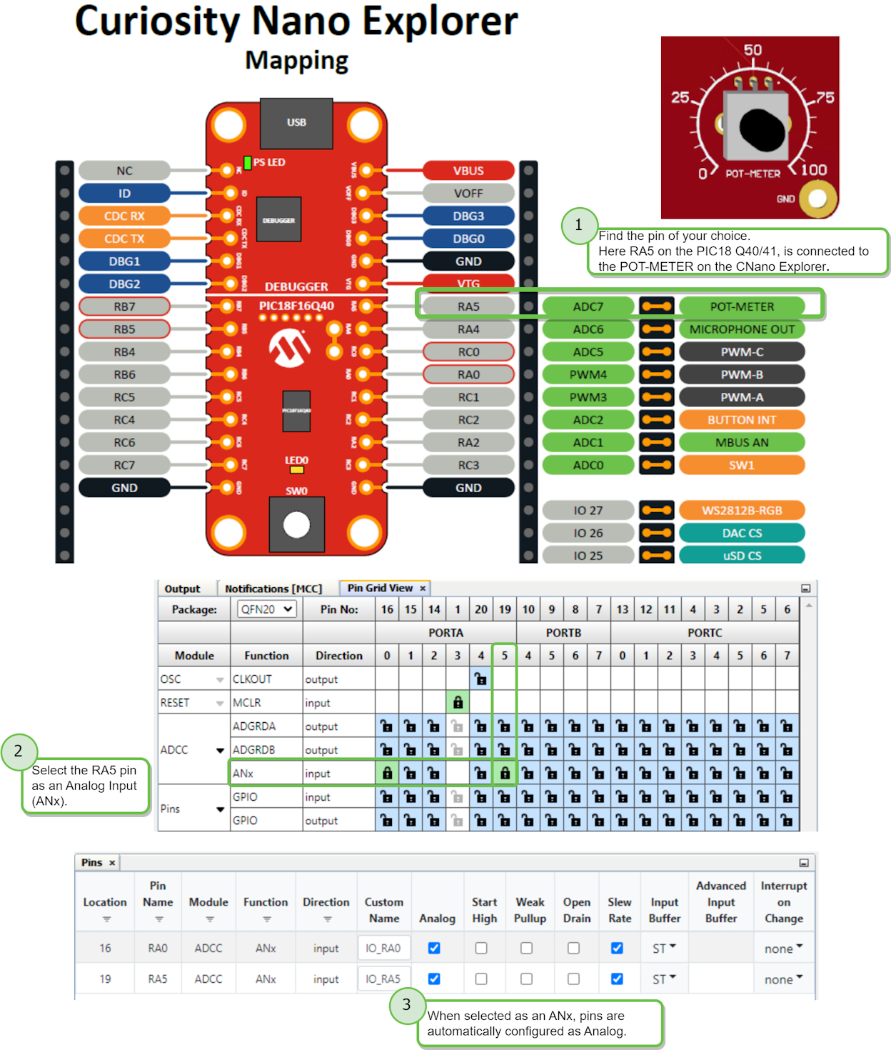
5.1.7.3 MCC Melody GPIO: Configuring Analog Input Pins
- Choose the ANx pin. From the development board, or your own schematic, select a pin.
- Configure the ANx pin as either input (e.g., ADC) or output (e.g., DAC).
- More configuration options are available in the Pins window.
adc_channel_t type, which is used in APIs related to taking
ADC conversions. 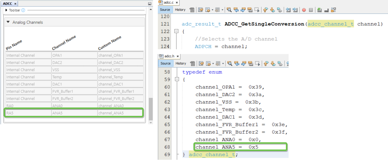
5.1.8 MCC Melody Timer
Tips related to Timer configuration, when using either Driver or PLIB.
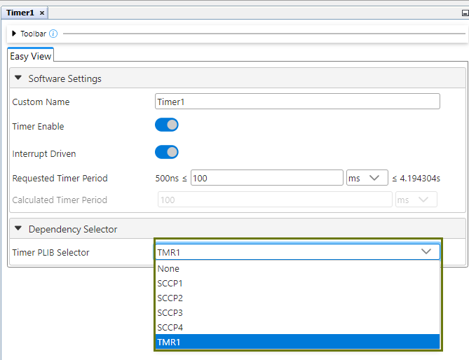
5.1.8.1 MCC Melody Timer PLIBs - Setting Period
This section details considerations related to Timer configuration when setting a required period.
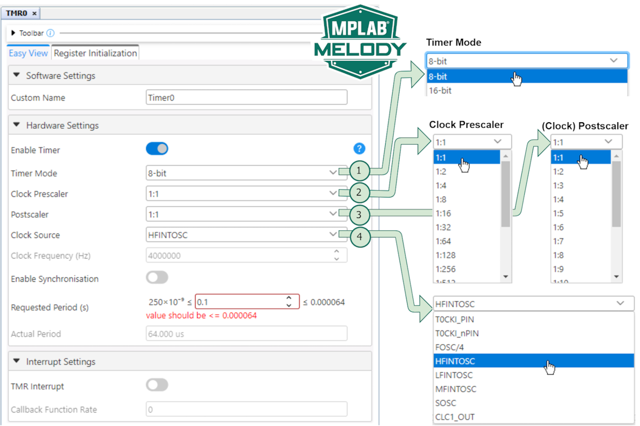
The Timers in MCC Melody are smarter than you may think. When configuring a Timer PLIBs in Melody, start by setting the value for the Requested Period (s), where ’s’ is in seconds, then ensure that Miniumum Period ≤ Requested Period(s) ≤ Max Period by adjusting:
- Timer Mode - e.g., 8-bit vs 16-bit (the 8-bit counts to 256, leading to a shorter period than the 16-bit, which counts to 65,536).
- Clock Prescaler - Divides the input to the Timer from the selected Clock Source.
- Postscaler - Divides the output frequency of the Timer by the selected ratio.
- Clock Source - These are the various clocks from which the Timer can be clocked.
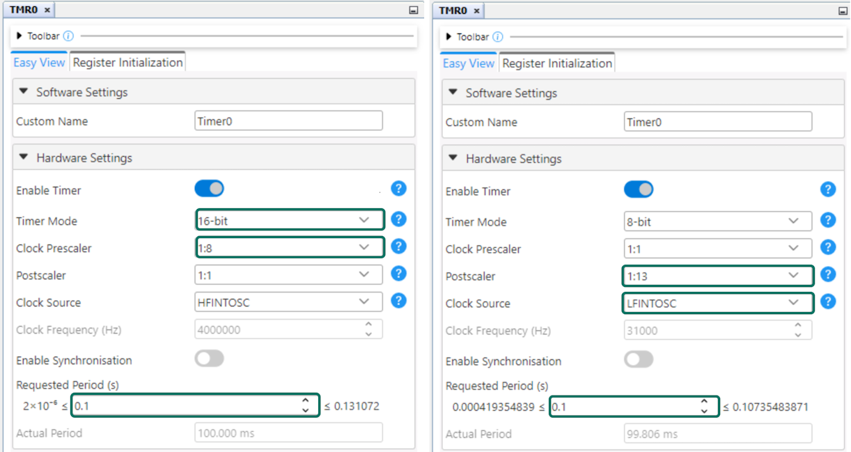
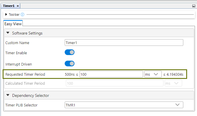
For example, below are two of the many ways in which the desired period of 100 ms (0.1s) can be achieved:
5.1.8.2 MCC Melody Timer Driver - Setting Period
This section details considerations related to Timer Driver configuration when setting a required period.
Configuring the Timer Driver can be done in multiple ways:
Multiple PLIBs may be available. One can be chosen to assign hardware for use by the driver.
Multiple units of time are available within the driver:
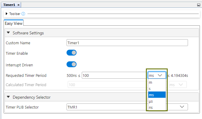
As an example, setting the timer period to 100 ms can be accomplished in this way:
5.1.9 MCC Melody Notifications
This section details the hints, warnings and errors from MPLAB® Code Configurator (MCC) Melody.
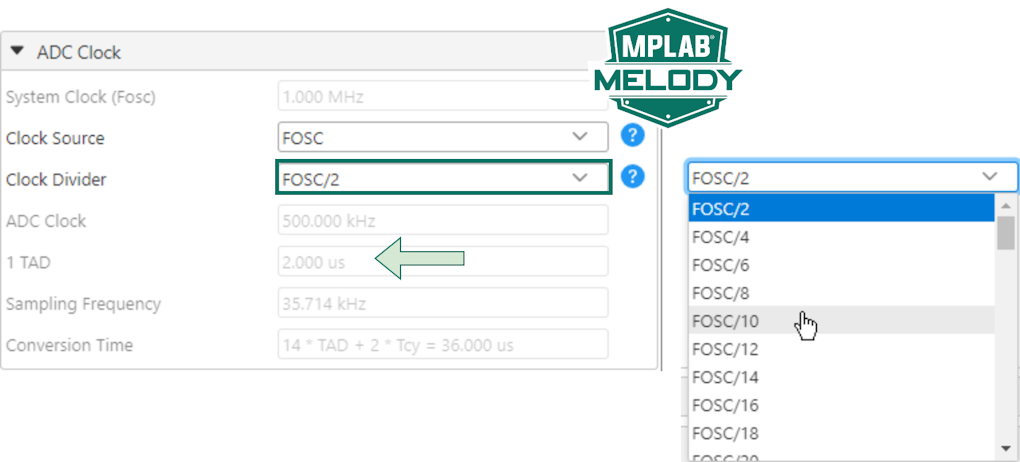
5.1.9.1 MCC Melody Hint: Slow Down ADC
Lower the ADC sampling frequency to be less the time it takes for an ADC Conversion (Tad).

How to fix it: ADCC Clock>Clock Divider>Slow down ADC Clock.
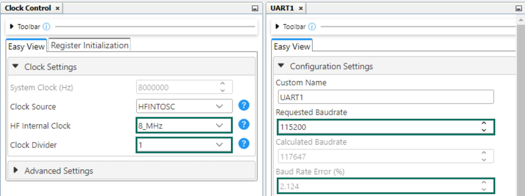
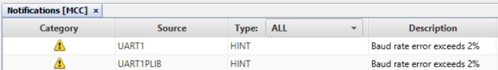
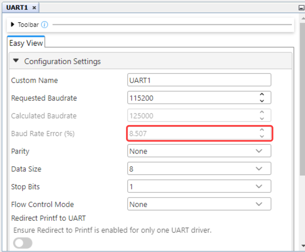
5.1.9.2 MCC Melody UART Driver: Correcting Baud Rate Error
Low default clock frequncy may result in baud rate errors, such as when setting a baud rate of 115200.
The default System Clock of the a number of PIC microcontrollers is 1 MHz (4 MHz / 4).
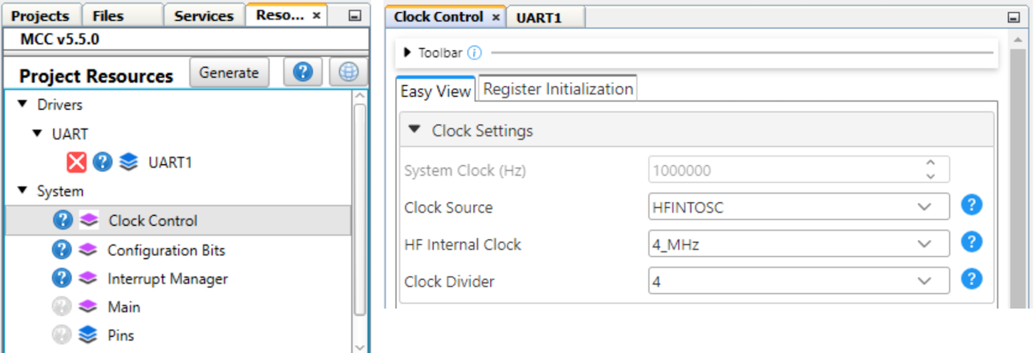
The System Clock can be in increased by increasing the clock frequency and/or reducing the Clock Divider.