
1.5 Digital Timing of the Watchdog Timer
The WDT is operating in a different clock domain than the CPU and synchronization between the two domains should be considered when using the WDT.
It takes up to three WDT clock cycles and three CPU clock cycles to configure the WDT. When configuration settings are written to the WDT control registers (CTRL and WINCTRL), the new configuration becomes effective from the next WDT clock edge (rising edge of WDT clock in Figure 1-3), i.e., between 4ms and 5ms after the configuration is written (three WDT clock cycles and three CPU clock cycles means it takes up to 4-5ms depending on how fast the CPU clock is running, while WDT is running at 1kHz clock frequency). This means that the initial timeout period is up to 5ms longer than the specified timeout. If the specified timeout is 8ms, the actual timeout will be between 12ms and 13ms. This will be relevant when using the Window mode and short timeout periods. This characteristic is not unique to the WDT: All asynchronous timers operate in this way due to synchronization between clock domains.
Again, the WDT is Reset when a valid write access to the control registers is performed (refer to section Run-time Enabling of the Watchdog Timer for further details).
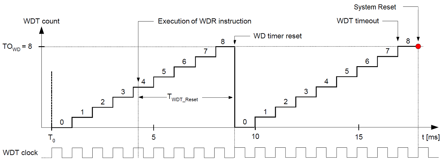
Another timing characteristic is that the duration between the execution
of the Watchdog Timer Reset instruction (WDR) and the actual resetting of
the WDT, is subject to synchronization between clock domains. The WDT is Reset on the third
WDT clock edge after the WDR is executed (see TWDT_Reset in Figure 1-3), which means that the WDT is Reset between 4ms and 5ms
after the WDR instruction is executed. Considering the use of a 8ms
timeout period, the first WDR instruction should be executed within 3ms
after enabling the WD. Taking the ±30% accuracy of the ULP oscillator into account, the
WDR instruction must be executed within 2.1ms or less. The interval
between subsequent WDR instructions should be 4.9ms or less (8ms – 1ms
uncertainty – 30% oscillator uncertainty). The effect of this synchronization is minimized
when the timeout period increases. This strongly indicates that using the Window mode in
combination with short timeout periods requires very strict timing.
If the WDT causes a system Reset, e.g., by timing out, the system Reset occurs on the first following WDT clock edge (see Figure 1-3). This means that the system Reset occurs 1ms after the WDT timeout period has expired. This normally does not cause a problem, but it is useful to know if trying to measure the WD timeout period by monitoring the logic level of a pin. A better way to determine the actual frequency of the WDT clock is to use the XMEGA Real Time Clock timer, which can be clocked by the ULP oscillator.
All of the above mentioned conditions apply to both the WDT Normal mode timeout and the WDT Window mode timeouts.