
3.3.5 PLC Coupling Circuitry Description
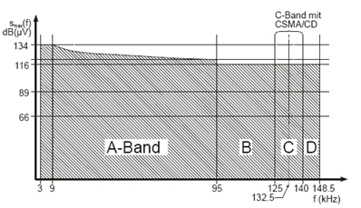
The European regulations concerning Power Line Communications are described in CENELEC standard EN 50065. This standard applies to electrical equipment using signals in the frequency range 3 kHz to 148,5 kHz to transmit information on low voltage electrical systems, either on the public supply system or within installations in consumers' premises. The following figure shows the different frequency bands allocated to the different applications.
FCC section 15 defined 10-490 kHz frequency band for PLC in North America and Canada. The FCC band (10-490 kHz), is not yet regulated in Europe.
PLC COUP011 is designed to communicate in FCC band, from 151 to 471 kHz.
The PL360G55CF-EK evaluation board communicates in the CENELEC A-Band and FCC Band frequencies. The use of frequencies in these bands shall be restricted to consumer use; for example, for end-user applications such as industrial applications.
Microchip has designed four coupling reference designs for this frequency range with variations in the BOM cost and the communication performance. Table 3-12 summarizes the main features of the available designs.
| Board Name | Description | Frequency Band (kHz) | Branch | Electrical Isolation | PRIME Channel | G3-PLC Band | Applicable Regulation |
|---|---|---|---|---|---|---|---|
| PLCOUP007-ISO | G3-PLC CENELEC A & PRIME Channel 1 compliant | 35 - 91 | Single | Yes | 1 | G3 CENELEC A | CENELEC EN 50065 |
| PLCOUP008-NONISO | Non-Isolated G3-PLC CENELEC A & PRIME Channel 1 compliant | 35 - 91 | Single | No | 1 | G3 CENELEC A | CENELEC EN 50065 |
| PLCOUP011-ISO | Dual PRIME / G3 for CENELEC A and FCC bands |
35 - 91 151-472 | Double | Yes | 1, 3, 4, 5, 6, 7 and 8 | G3 CENELEC A and FCC | CENELEC EN 50065 |
| PLCOUP011-NONISO | Non-Isolated Dual PRIME / G3 for CENELEC A and FCC bands |
35 - 91 151-472 | Double | No | 1, 3, 4, 5, 6, 7 and 8 | G3 CENELEC A and FCC | CENELEC EN 50065 |
The PL360G55CF-EK board is assembled with the PLCOUP011-ISO coupling design. The goal is to provide a cost-optimized fully-featured design according to the G3-PLC and PRIME requirements. Still, the PL360G55CF-EK board is designed to allow using all the other coupling designs by changing the corresponding components and firmware configurations.
- Transmission Stage
- Transmission Stage for CENELEC A-Band
- Transmission Stage for FCC Band
- Filtering Stage
- Filtering Stage for CENELEC A-Band
- Filtering Stage for FCC Band
- Coupling Stage
- Reception Stage
The following sections describe the purpose of every sub-circuit assembled in the PL360G55CF-EK board.