1.2.4.3 Configuring the Library
PVDD Monitor Service Specific User Configurations
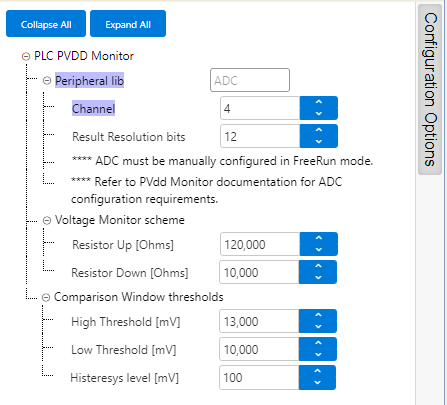
PVDD Monitor Service library is configured through MCC. Below is the figure of the MCC configuration window for PVDD Monitor Service and brief description.
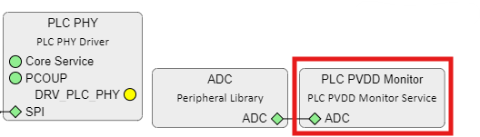
- Peripheral lib:
- Indicates the ADC peripheral instance used by the PVDD Monitor Service
- The name of the peripheral will vary from device to device
- Channel:
- ADC channel to use with PVDD Monitor Service according to the HW board design
- PL460 Evaluation
Kit has been designed to provide a Supply Monitor pin through
the Xplained PRO connector
Figure 1-52. PL460-EK Xplained PRO Connector 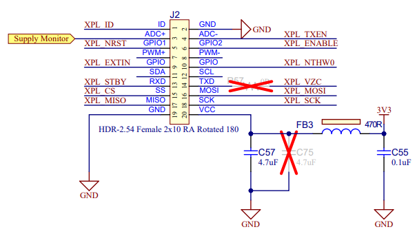
- This Supply Monitor pin is connected to the ADC peripheral, so that connection determines which ADC channel is used
- Result resolution
bits:
- ADC conversion resolution
- Voltage Monitor hardware
configuration:
- PL460-EK evaluation kit
includes a specific circuit to monitor VDD voltage
Figure 1-53. PL460-EK Supply Monitor 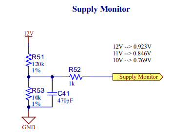
- Resistor Up:
- Value in ohms of the HW resistor connected to VDD. In case of PL460-EK, it is R51
- Resistor Down:
- Value in ohms of the HW resistor connected to GND. In case of PL460-EK, it is R53
- PL460-EK evaluation kit
includes a specific circuit to monitor VDD voltage
- Comparison Window
thresholds:
- Threshold values to
configure the comparison window of the PVDD Monitor service
- High
Threshold:
- The PLC transmission shall not take place when the PVDD level is above the high threshold value
- Low Threshold:
- The PLC transmission shall not take place when the PVDD level is under the low threshold value
- Hysteresis
Level:
- Hysteresis window below high threshold and above low threshold, to avoid bouncing when voltage is near thresholds
- High
Threshold:
- Threshold values to
configure the comparison window of the PVDD Monitor service
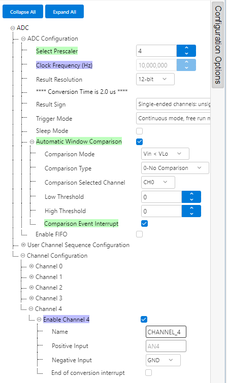
ADC Configurations
There are some configuration values which must be adjusted manually in ADC PLIB configuration options to match the values configured in PVDD Monitor service. These configuration values are the following:
- Prescaler and Result Resolution must be set.
- Conversion mode must be configured in FreeRun mode.
- Enable the proper channel according to the board HW design.
- If Automatic Window Comparison is available, enable it and its Comparison Event Interrupt. Otherwise, ADC End of Conversion Interrupt must be enabled.