
1.2.6.3 Configuring the Library
USI Service is configured through MCC. The following figures show the MCC configuration window for USI Service and brief description.
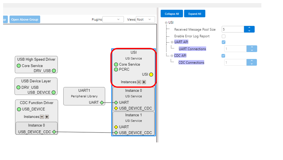
- Received Message Pool Size
- Specifies the maximum number of received USI messages (of any length) that can be stored, without calling SRV_USI_Tasks, for all instances using UART (not used for instances using USB CDC)
- Enable Error Log Report
- Enables the error log report
- UART API
- UART Connections
- Indicates the number of USI instances using UART
- UART Connections
- CDC API
- CDC Connections
- Indicates the number of USI instances using USB CDC
- CDC Connections
Each USI instance can be connected to:
- Peripheral Library with UART capability (UART/USART/FLEXCOM/SERCOM)
- USB CDC Function Driver (USB_DEVICE_CDC capability)
The user must connect only one dependency to each USI instance. Although it is allowed in MCC to connect an instance to both UART and USB_DEVICE_CDC, it is not supported by the library and the code will not be generated properly.
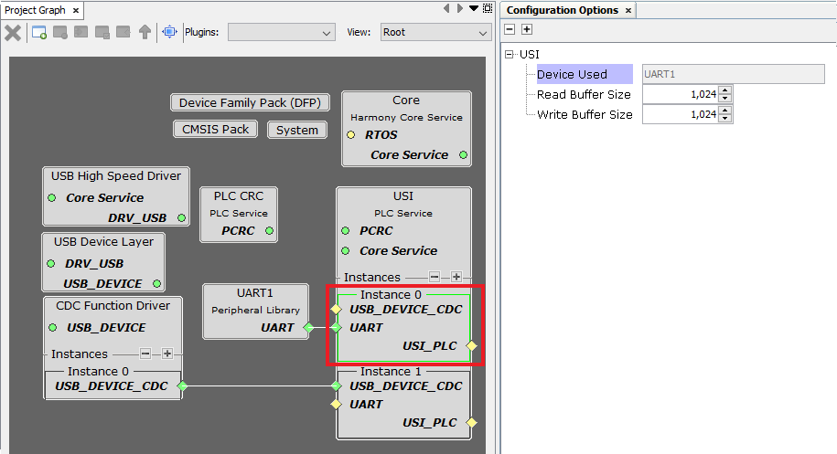
- Device Used
- Indicates the hardware PLIB instance used by the corresponding instance of USI Service
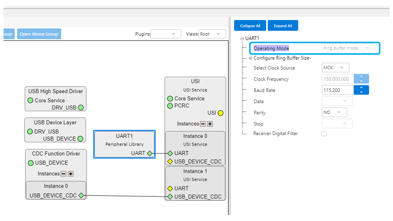
- The underlying PLIB is automatically configured in Non-blocking mode, as shown in the figure below
- Read Buffer Size
- Size in bytes of the buffer used by the corresponding USI instance for message reception
- Note that the buffer can store more than one received message (Received Message Pool Size) if a new message is received before calling SRV_USI_Tasks
- Write Buffer Size
- Size in bytes of the buffer used by the corresponding USI instance for message transmission
- Note that USI adds overhead (start/end marks, USI header, escaped characters) to the message sent to SRV_USI_Send_Message
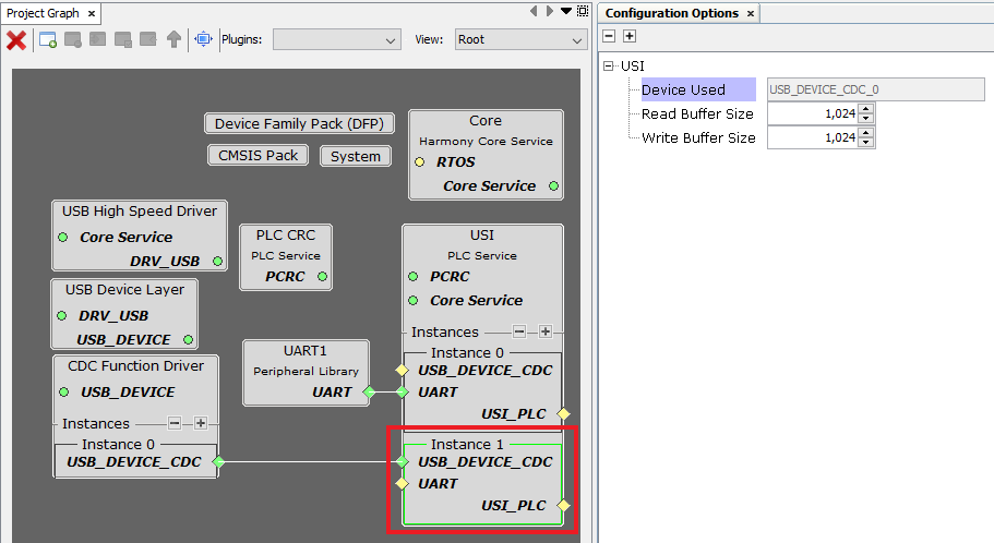
- Device Used
- Indicates the USB CDC Instance used by the corresponding instance of USI Service
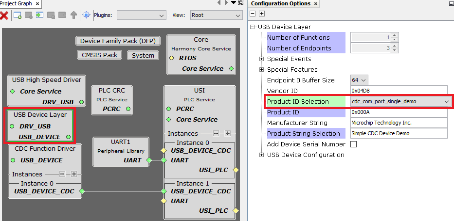
- The user should configure
cdc_com_port_single_demoin the USB Device Layer module, as shown in the figure below
- Read Buffer Size
- Size in bytes of the buffer used by the corresponding USI instance for message reception
- Write Buffer Size
- Size in bytes of the buffer used by the corresponding USI instance for message transmission
- Note that USI adds overhead (start/end marks, USI header, escaped characters) to the message sent to SRV_USI_Send_Message
- RTOS Settings
- Stack Size (in bytes):
- Specifies the number of bytes to be allocated on the stack for the service task
- Task Priority:
- Specifies priority for the service task thread. The value can vary based on RTOS used.
- Stack Size (in bytes):