
2.2.5.1.2 Manual Calibration
The calibration constants must be calculated according to the metrology library documentation. A spreadsheet is included in the distribution package to make the procedure easier. This spreadsheet calculates the proper values of the CAL_x registers and generates the commands to be sent to the board through the serial console to update the registers. This section explains how to calibrate the board using the spreadsheet. These are the steps to follow:
- Follow the instructions described in the previous chapter, ensuring that the board is properly configured, paying special attention to the configuration related to the hardware connected to the metrology inputs.
- Open the
METROLOGY_CONFIGURE_CALIBRATE_CALCULATE.xlsx spreadsheet, and go to the
"Step-by-step guide" sheet, and follow the steps. Note: The steps described can change depending on the version of the Excel file.
- Configure the input sources and the meter tester if used (meter form, voltage, current, and so on). In this example, a PIC32CXMTC board + MCP3914 EB will be calibrated using a WECO tester, configured to generate 30A and 220V to each phase, at 50 Hz. Phase shift between voltage vectors is 120º, and phase shift between voltage and current vectors is 60º for each phase, but any convenient values of voltage, current and phase angle may be used.
- Write these values in the yellow
cells.
Figure 2-57. Input Sources Configuration 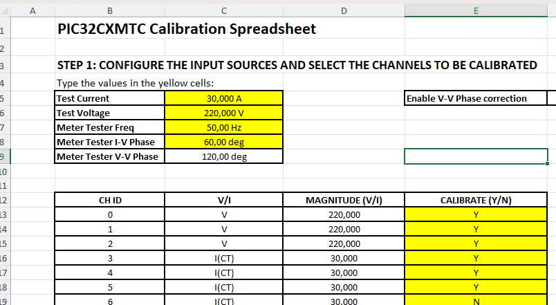
- Set the calibration constants to the
default values (unity gain and zero phase adjustments). To do that, copy the
following DCM command lines to the metrology console:
Figure 2-58. Set Default Values as Groups 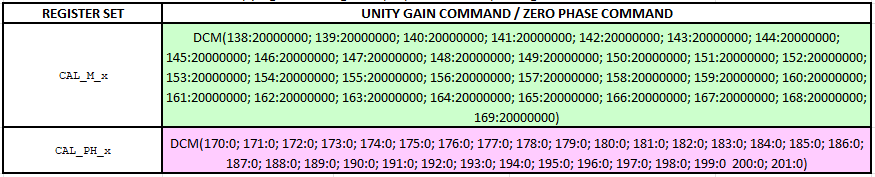
>DCM(138:20000000; 139:20000000; 140:20000000; 141:20000000; 142:20000000; 143:20000000; 144:20000000; 145:20000000; 146:20000000; 147:20000000; 148:20000000) Set 138 Is Ok ! Set 139 Is Ok ! Set 140 Is Ok ! Set 141 Is Ok ! Set 142 Is Ok ! Set 143 Is Ok ! Set 144 Is Ok ! Set 145 Is Ok ! Set 146 Is Ok ! Set 147 Is Ok ! Set 148 Is Ok ! >DCM(149:20000000; 150:20000000; 151:20000000; 152:20000000; 153:20000000; 154:20000000; 155:20000000; 156:20000000; 157:20000000; 158:20000000; 159:20000000) Set 149 Is Ok ! Set 150 Is Ok ! Set 151 Is Ok ! Set 152 Is Ok ! Set 153 Is Ok ! Set 154 Is Ok ! Set 155 Is Ok ! Set 156 Is Ok ! Set 157 Is Ok ! Set 158 Is Ok ! Set 159 Is Ok ! >DCM(160:20000000; 161:20000000; 162:20000000; 163:20000000; 164:20000000; 165:20000000; 166:20000000; 167:20000000; 168:20000000; 169:20000000) Set 160 Is Ok ! Set 161 Is Ok ! Set 162 Is Ok ! Set 163 Is Ok ! Set 164 Is Ok ! Set 165 Is Ok ! Set 166 Is Ok ! Set 167 Is Ok ! Set 168 Is Ok ! Set 169 Is Ok ! >DCM(170:0; 171:0; 172:0; 173:0; 174:0; 175:0; 176:0; 177:0; 178:0; 179:0; 180:0) Set 170 Is Ok ! Set 171 Is Ok ! Set 172 Is Ok ! Set 173 Is Ok ! Set 174 Is Ok ! Set 175 Is Ok ! Set 176 Is Ok ! Set 177 Is Ok ! Set 178 Is Ok ! Set 179 Is Ok ! Set 180 Is Ok ! >DCM(181:0; 182:0; 183:0; 184:0; 185:0; 186:0; 187:0; 188:0; 189:0; 190:0; 191:0) Set 181 Is Ok ! Set 182 Is Ok ! Set 183 Is Ok ! Set 184 Is Ok ! Set 185 Is Ok ! Set 186 Is Ok ! Set 187 Is Ok ! Set 188 Is Ok ! Set 189 Is Ok ! Set 190 Is Ok ! Set 191 Is Ok ! >DCM(192:0; 193:0; 194:0; 195:0; 196:0; 197:0; 198:0; 199:0 200:0; 201:0) Set 192 Is Ok ! Set 193 Is Ok ! Set 194 Is Ok ! Set 195 Is Ok ! Set 196 Is Ok ! Set 197 Is Ok ! Set 198 Is Ok ! Set 199 Is Ok ! Set 200 Is Ok ! Set 201 Is Ok ! > - Energize the board, applying the established configuration (in the WECO software, this is done through the JOG command), and wait for the meter tester to stabilize the voltage and current sources.
- On Terminal, enter the following
commands: PAR CH, PAR A, DCR, DSR and DAR. Then, copy and paste the results to the
blue cells:
Figure 2-59. Read Channel Measurements (Command PAR CH) 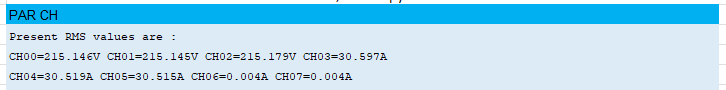
Figure 2-60. Read Angle Measurements (Command PAR A) 
Figure 2-61. Read DSP_CONTROL Registers (Command DCR) 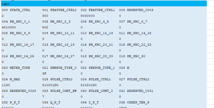
Figure 2-62. Read DSP_STATUS Register (Command DSR) 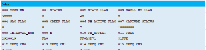
Figure 2-63. Read DSP_ACC Register (Command DAR) 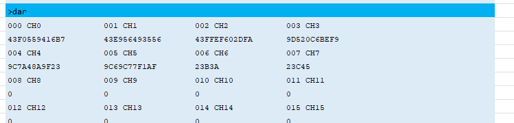
- The spreadsheet calculates the
calibration constants (the CAL_x registers) and generates the commands to be sent to
the board through the serial console. The user can choose between:
- Sending the calibration
constants as groups using the DCM command; able to send multiple commands at
the same time. To do that, copy the green and purple cells to the metrology
console.
Figure 2-64. Set Calibration Constants as Groups 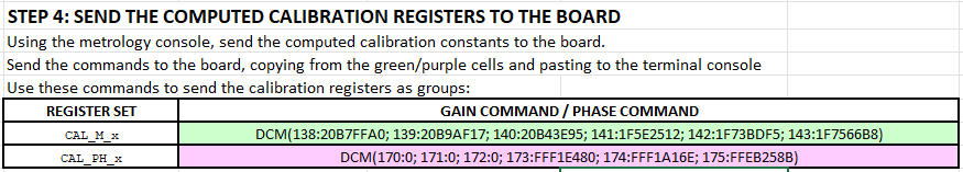
>DCM(138:20B7FFA0; 139:20B9AF17; 140:20B43E95; 141:1F5E2512; 142:1F73BDF5; 143:1F7566B8)
Set 138 Is Ok !
Set 139 Is Ok !
Set 140 Is Ok !
Set 141 Is Ok !
Set 142 Is Ok !
Set 143 Is Ok !
>DCM(170:0; 171:0; 172:0; 173:FFF1E480; 174:FFF1A16E; 175:FFEB258B)
Set 170 Is Ok !
Set 171 Is Ok !
Set 172 Is Ok !
Set 173 Is Ok !
Set 174 Is Ok !
Set 175 Is Ok !

>
- Sending the calibration
constants as groups using the DCM command; able to send multiple commands at
the same time. To do that, copy the green and purple cells to the metrology
console.
- Read the control registers (command
DCR) to check that the calibration registers were successfully updated (values in
bold):
>dcr 000 STATE_CTRL 001 FEATURE_CTRL0 002 FEATURE_CTRL1 003 RESERVED_C003 2 300 8000000 0 004 PH_SRC_0_1 005 PH_SRC_2_3 006 PH_SRC_4_5 007 PH_SRC_6_7 4010300 502 0 0 008 PH_SRC_8_9 009 PH_SRC_10_11 010 PH_SRC_12_13 011 PH_SRC_14_15 0 0 0 0 012 PH_SRC_16_17 013 PH_SRC_18_19 014 PH_SRC_20_21 015 PH_SRC_22_23 0 0 0 0 016 PH_SRC_24_25 017 PH_SRC_26_27 018 PH_SRC_28_29 019 PH_SRC_30 0 0 0 0 020 METER_TYPE 021 SENSOR_TYPE_0 022 SENSOR_TYPE_1 023 M 0 3F 0 0 024 N_MAX 025 PULSE_CTRL0 026 PULSE_CTRL1 027 PULSE_CTRL2 1130 810001D0 810201D0 0 028 RESERVED_C028 029 PULSE_CONT_PW 030 PULSE_CONT_I 031 RESERVED_C031 0 7 0 0 032 P_K_T 033 Q_K_T 034 I_K_T 035 CREEP_THR_P 500000 500000 500000 2E9A 036 CREEP_THR_Q 037 CREEP_THR_I 038 P_PW_OS_CTRL 039 Q_PW_OS_CTRL 2E9A 212D 0 0 040 POWER_OFFSET_P 041 POWER_OFFSET_Q 042 SWELL_OV_TH_00 043 SWELL_OV_TH_01 0 0 5E84F62 5E84F62 044 SWELL_OV_TH_02 045 SWELL_OV_TH_03 046 SWELL_OV_TH_04 047 SWELL_OV_TH_05 5E84F62 0 0 0 048 SWELL_OV_TH_06 049 SWELL_OV_TH_07 050 SWELL_OV_TH_08 051 SWELL_OV_TH_09 0 0 0 0 052 SWELL_OV_TH_10 053 SWELL_OV_TH_11 054 SWELL_OV_TH_12 055 SWELL_OV_TH_13 0 0 0 0 056 SWELL_OV_TH_14 057 SWELL_OV_TH_15 058 SWELL_OV_TH_16 059 SWELL_OV_TH_17 0 0 0 0 060 SWELL_OV_TH_18 061 SWELL_OV_TH_19 062 SWELL_OV_TH_20 063 SWELL_OV_TH_21 0 0 0 0 064 SWELL_OV_TH_22 065 SWELL_OV_TH_23 066 SWELL_OV_TH_24 067 SWELL_OV_TH_25 0 0 0 0 068 SWELL_OV_TH_26 069 SWELL_OV_TH_27 070 SWELL_OV_TH_28 071 SWELL_OV_TH_29 0 0 0 0 072 SWELL_OV_TH_30 073 SWELL_OV_TH_31 074 SAG_THRES_00 075 SAG_THRES_01 0 0 1A2EC26 1A2EC26 076 SAG_THRES_02 077 SAG_THRES_03 078 SAG_THRES_04 079 SAG_THRES_05 1A2EC26 0 0 0 080 SAG_THRES_06 081 SAG_THRES_07 082 SAG_THRES_08 083 SAG_THRES_09 0 0 0 0 084 SAG_THRES_10 085 SAG_THRES_11 086 SAG_THRES_12 087 SAG_THRES_13 0 0 0 0 088 SAG_THRES_14 089 SAG_THRES_15 090 SAG_THRES_16 091 SAG_THRES_17 0 0 0 0 092 SAG_THRES_18 093 SAG_THRES_19 094 SAG_THRES_20 095 SAG_THRES_21 0 0 0 0 096 SAG_THRES_22 097 SAG_THRES_23 098 SAG_THRES_24 099 SAG_THRES_25 0 0 0 0 100 SAG_THRES_26 101 SAG_THRES_27 102 SAG_THRES_28 103 SAG_THRES_29 0 0 0 0 104 SAG_THRES_30 105 SAG_THRES_31 106 K_00 107 K_01 0 0 19CC00 19CC00 108 K_02 109 K_03 110 K_04 111 K_05 19CC00 9A523 9A523 9A523 112 K_06 113 K_07 114 K_08 115 K_09 9A523 9A523 0 0 116 K_10 117 K_11 118 K_12 119 K_13 0 0 0 0 120 K_14 121 K_15 122 K_16 123 K_17 0 0 0 0 124 K_18 125 K_19 126 K_20 127 K_21 0 0 0 0 128 K_22 129 K_23 130 K_24 131 K_25 0 0 0 0 132 K_26 133 K_27 134 K_28 135 K_29 0 0 0 0 136 K_30 137 K_31 138 CAL_M_00 139 CAL_M_01 0 0 20B7FFA0 20B9AF17 140 CAL_M_02 141 CAL_M_03 142 CAL_M_04 143 CAL_M_05 20B43E95 1F5E2512 1F73BDF5 1F7566B8 144 CAL_M_06 145 CAL_M_07 146 CAL_M_08 147 CAL_M_09 20000000 20000000 20000000 20000000 148 CAL_M_10 149 CAL_M_11 150 CAL_M_12 151 CAL_M_13 20000000 20000000 20000000 20000000 152 CAL_M_14 153 CAL_M_15 154 CAL_M_16 155 CAL_M_17 20000000 20000000 20000000 20000000 156 CAL_M_18 157 CAL_M_19 158 CAL_M_20 159 CAL_M_21 20000000 20000000 20000000 20000000 160 CAL_M_22 161 CAL_M_23 162 CAL_M_24 163 CAL_M_25 20000000 20000000 20000000 20000000 164 CAL_M_26 165 CAL_M_27 166 CAL_M_28 167 CAL_M_29 20000000 20000000 20000000 20000000 168 CAL_M_30 169 CAL_M_31 170 CAL_PH_00 171 CAL_PH_01 20000000 20000000 0 0 172 CAL_PH_02 173 CAL_PH_03 174 CAL_PH_04 175 CAL_PH_05 0 FFF1E480 FFF1A16E FFEB258B 176 CAL_PH_06 177 CAL_PH_07 178 CAL_PH_08 179 CAL_PH_09 0 0 0 0 180 CAL_PH_10 181 CAL_PH_11 182 CAL_PH_12 183 CAL_PH_13 0 0 0 0 184 CAL_PH_14 185 CAL_PH_15 186 CAL_PH_16 187 CAL_PH_17 0 0 0 0 188 CAL_PH_18 189 CAL_PH_19 190 CAL_PH_20 191 CAL_PH_21 0 0 0 0 192 CAL_PH_22 193 CAL_PH_23 194 CAL_PH_24 195 CAL_PH_25 0 0 0 0 196 CAL_PH_26 197 CAL_PH_27 198 CAL_PH_28 199 CAL_PH_29 0 0 0 0 200 CAL_PH_30 201 CAL_PH_31 202 CAPTURE_CTRL 203 CAPTURE_CH_SEL 0 0 0 0 204 CAPT_BUFF_SIZE 205 CAPTURE_ADDR 206 RESERVED_C206 207 RESERVED_C207 0 0 0 0 208 RESERVED_C208 209 MCP_GAIN0 210 MCP_GAIN1 211 MCP_GAIN2 0 0 0 0 212 MCP_GAIN3 213 MCP_CONFIG0 214 MCP_CONFIG1 215 MCP_CONFIG2 0 384050 384050 0 216 MCP_CONFIG3 217 RESERVED_C217 218 PW_OFFSET_P_00 219 PW_OFFSET_P_01 0 0 0 0 220 PW_OFFSET_P_02 221 PW_OFFSET_P_03 222 PW_OFFSET_P_04 223 PW_OFFSET_P_05 0 0 0 0 224 PW_OFFSET_P_06 225 PW_OFFSET_P_07 226 PW_OFFSET_P_08 227 PW_OFFSET_P_09 0 0 0 0 228 PW_OFFSET_P_10 229 PW_OFFSET_P_11 230 PW_OFFSET_P_12 231 PW_OFFSET_P_13 0 0 0 0 232 PW_OFFSET_P_14 233 PW_OFFSET_P_15 234 PW_OFFSET_P_16 235 PW_OFFSET_P_17 0 0 0 0 236 PW_OFFSET_P_18 237 PW_OFFSET_P_19 238 PW_OFFSET_P_20 239 PW_OFFSET_P_21 0 0 0 0 240 PW_OFFSET_P_22 241 PW_OFFSET_P_23 242 PW_OFFSET_P_24 243 PW_OFFSET_P_25 0 0 0 0 244 PW_OFFSET_P_26 245 PW_OFFSET_P_27 246 PW_OFFSET_P_28 247 PW_OFFSET_P_29 0 0 0 0 248 PW_OFFSET_P_30 249 RESERVED_C249 250 PW_OFFSET_Q_00 251 PW_OFFSET_Q_01 0 0 0 0 252 PW_OFFSET_Q_02 253 PW_OFFSET_Q_03 254 PW_OFFSET_Q_04 255 PW_OFFSET_Q_05 0 0 0 0 256 PW_OFFSET_Q_06 257 PW_OFFSET_Q_07 258 PW_OFFSET_Q_08 259 PW_OFFSET_Q_09 0 0 0 0 260 PW_OFFSET_Q_10 261 PW_OFFSET_Q_11 262 PW_OFFSET_Q_12 263 PW_OFFSET_Q_13 0 0 0 0 264 PW_OFFSET_Q_14 265 PW_OFFSET_Q_15 266 PW_OFFSET_Q_16 267 PW_OFFSET_Q_17 0 0 0 0 268 PW_OFFSET_Q_18 269 PW_OFFSET_Q_19 270 PW_OFFSET_Q_20 271 PW_OFFSET_Q_21 0 0 0 0 272 PW_OFFSET_Q_22 273 PW_OFFSET_Q_23 274 PW_OFFSET_Q_24 275 PW_OFFSET_Q_25 0 0 0 0 276 PW_OFFSET_Q_26 277 PW_OFFSET_Q_27 278 PW_OFFSET_Q_28 279 PW_OFFSET_Q_29 0 0 0 0 280 PW_OFFSET_Q_30 281 RESERVED_C281 0 0 > - Wait for about 2 seconds to let the DSP data to be stabilized.
- On Terminal, enter PAR commands to read the measurements and check that the obtained values are accurate.
- Repeat steps 8 through 12 to recalibrate the meter again if the accuracy does not meet the specification requirement.
- When accuracy meets the requirement,
save the calibration constants into non-volatile memory by using the terminal
command DCS.
>DCS
Save Data Is Ok !
>
Note: The command DCD allows the default calibration and configuration
settings from the firmware (constant values stored in the application code) to be
loaded. Otherwise, the system will always be booting up with the calibration values
stored in non-volatile memory.