1.36 TRAM Erase On Tamper Detect
This example application shows how to configure and use tamper detect feature of RTC and TrustRam.
Description
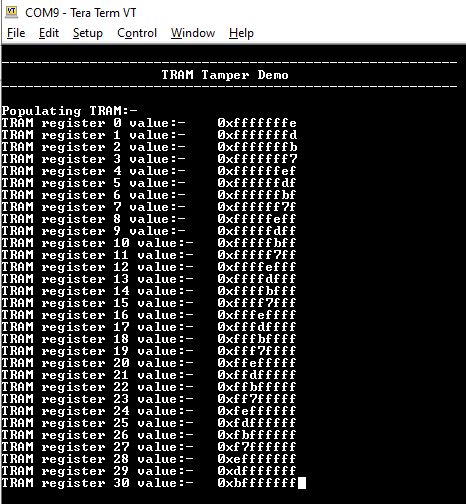
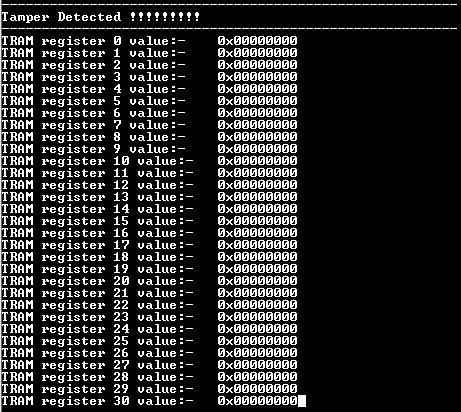
This example application shows how to setup and configure tamper detection using the RTC Peripheral Library. The application populates TrustRam with random data and then waits for tamper detection to happen. On Tamper detection, application displays the tamper detected and read the content of the TrustRam. The example demonstrates auto erase feature of the TrustRam when tamper is detected.
Downloading and Building the Application
To clone or download this application from Github, go to the main page of this repository and then click Clone button to clone this repository or download as zip file. This content can also be downloaded using content manager by following these instructions.
Path of the application within the repository is apps/tram/tram_tamper_erase/firmware.
To build the application, refer to the following table and open the project using its IDE.
| Project Name | Description |
|---|---|
| pic32ck_gc01_cult.X | MPLABX Project for PIC32CK GC01 Curiosity Ultra board |
Setting Up the Hardware
The following table shows the target hardware for the application projects.
| Project Name | Board |
|---|---|
| pic32ck_gc01_cult.X | PIC32CK GC01 Curiosity Ultra board |
Setting Up PIC32CK GC01 Curiosity Ultra Board
- Short RTC Input pin (EXT1, PIN 13) to Vcc
- Connect the Debug USB port on the board to the computer using a micro USB cable
Running the Application
- Open the Terminal application (Ex.:Tera term) on the computer
- Connect to the PKOB4 Virtual COM port and configure the serial settings as
follows:
- Baud : 115200
- Data : 8 Bits
- Parity : None
- Stop : 1 Bit
- Flow Control : None
- Build and Program the application using its IDE
- Console will print the value contained in the TRAM (Observe that the TRAM
contains non zero values)

- To emulate tampering, create a falling edge on the RTC input pin
- Short RTC Input pin to Vcc and then remove the short, and connect RTC
Input pin to GND to create a falling edge
Board RTC Input LED Name PIC32CK GC01 Curiosity Ultra board RTC Input 6 (EXT1, PIN 13) LED0
- Short RTC Input pin to Vcc and then remove the short, and connect RTC
Input pin to GND to create a falling edge
- Console will output the current value of TRAM (Observe that the TRAM values now
read zero indicating a erasure of the TRAM content)

