36.3 Common Programming Interfaces
Connection to a target device is typically done through an ICSP header. A commonly found connector on development tools is the RJ-11 in the 6P6C (6-pin, 6-connector) configuration. See Figure 36-1.
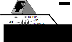
Pin Description*
1 = VPP/MCLR
2 = VDD Target
3 = VSS (ground)
4 = ICSPDAT
5 = ICSPCLK
6 = No Connect
Another connector often found in use with the PICkit™ programmers is a standard 6-pin header with 0.1 inch spacing. Refer to Figure 36-2.
For additional interface recommendations, refer to the specific device programmer manual prior to PCB design.
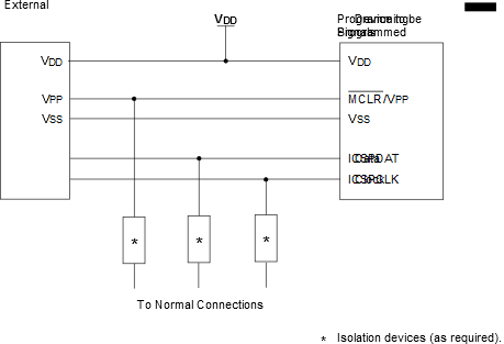
It is recommended that isolation devices be used to separate the programming pins from other circuitry. The type of isolation is highly dependent on the specific application and may include devices such as resistors, diodes, or even jumpers. See Figure 36-3 for more information.
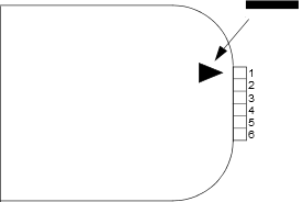
Pin Description(1)
1 = VPP/MCLR
2 = VDD Target
3 = VSS (ground)
4 = ICSPDAT
5 = ICSPCLK
6 = No Connect
-
Note: The 6-pin header (0.100" spacing) accepts 0.025" square pins.